> ## Documentation Index
> Fetch the complete documentation index at: https://dragonwingdocs-staging.qualcomm.com/llms.txt
> Use this file to discover all available pages before exploring further.
# DIP 开关、端口和接口
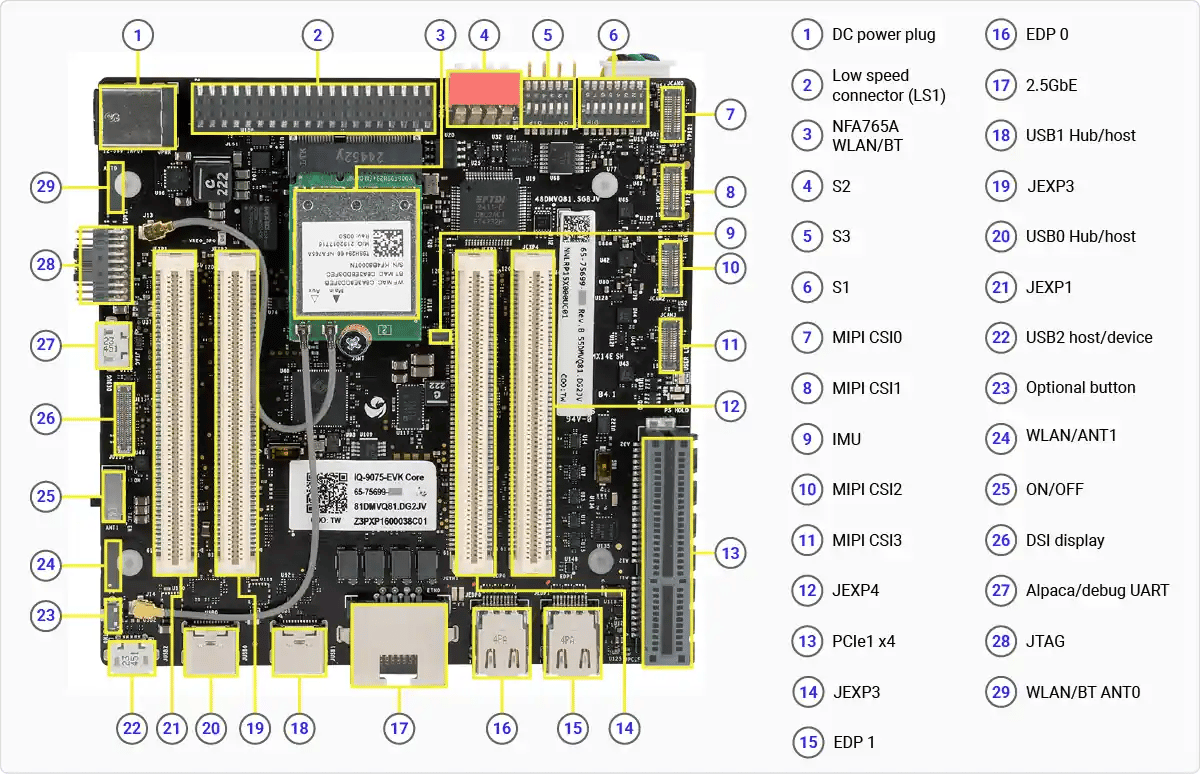
## 端口和接口
 ## DIP 开关
以下图片显示了主板上 DIP 开关的位置。
## DIP 开关
以下图片显示了主板上 DIP 开关的位置。
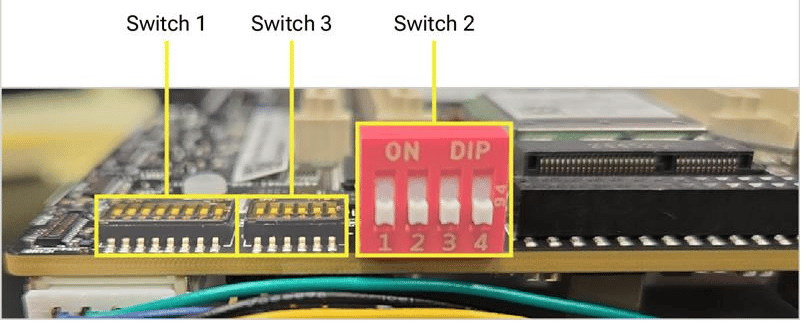
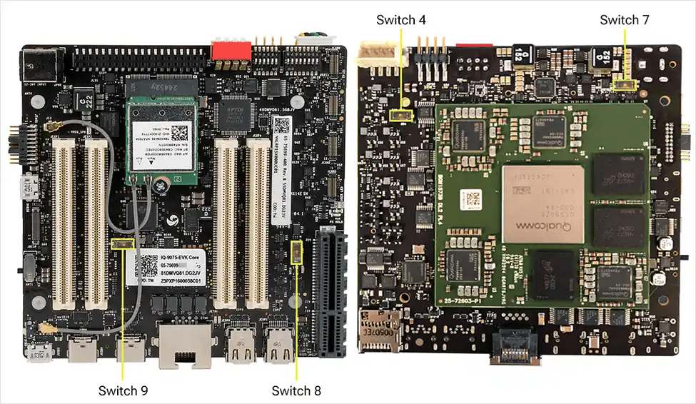 主板上的所有功能无需更改 DIP 开关即可运行。大的红色开关用于 EDL/Fastboot;下方较小的开关用于夹层板(mezzanine)。
| 开关 | ON 时的连接 | OFF 时的连接(出厂默认) |
| ----- | ------------------------------ | ----------------------------- |
| SW1-1 | PCIe0 路由到夹层板 | PCIe0 连接到主板 Wi-Fi 模块 |
| SW1-2 | PCIe1 路由到夹层板 | PCIe1 连接到主板 PCIe 连接器 |
| SW1-3 | SDIO 路由到夹层板 | SDIO 路由到主板 SD 卡 |
| SW1-4 | DSI 路由到主板柔性连接器 | DSI 路由到夹层板 |
| SW1-5 | CSI0 路由到夹层板 | CSI0 路由到主板 CSI 柔性连接器 |
| SW1-6 | CSI1 路由到夹层板 | CSI1 路由到主板 CSI 柔性连接器 |
| SW1-7 | CSI2 路由到夹层板 | CSI2 路由到主板 CSI 柔性连接器 |
| SW2-1 | 主域强制 USB 启动/EDL | 无影响 |
| SW2-2 | 主域快速启动 | 无影响 |
| SW2-3 | 主域和 Sail 域强制 USB 启动/EDL(组合) | 无影响 |
| SW2-4 | Sail 域 Fastboot 模式 | 无影响 |
| SW3-1 | OSPI 路由到夹层板 | OSPI 连接到 MCU 的板载存储器 |
| SW3-2 | 强制 MD 和 MCU PS\_HOLD | 无影响 |
| SW3-3 | 禁用看门狗 | 启用 RAM dump |
| SW3-4 | 从 eMMC 启动(位于接口板和夹层板上) | 从 UFS 启动 |
| SW3-5 | 启用 EUD | 无影响 |
| SW3-6 | 跳过 MD BIST | 无影响 |
| SW4-1 | 风扇 PWM-MODE 设置为低 | 风扇 PWM-MODE 设置为高 |
| SW7-1 | RGMII 电压选择 2.5V | RGMII 电压选择 1.8V |
| SW8-1 | USB 连接到夹层板上 NFA765 模块的 M.2 连接器 | USB 连接到主板上 NFA765 模块的 M.2 连接器 |
| SW9-1 | SAIL CAN GPIO 路由到夹层板 | SAIL CAN GPIO 路由到 JLS1 连接器 |
**SW2-1** 未在软件中启用。**SW2-3** 同时使两个域进入 EDL 模式——软件下载时需要此设置。
## 其他按钮和开关
* **侧面安装的滑动/拨动开关**(位置 25)是**主电源开/关**控制。要对设备进行断电重启或复位,拨动该开关即可——无需按下或长按任何按钮。
* 一个**小按钮**(位置 26)目前**未启用**。它连接到 **GPIO 6**,预留给未来的软件功能。
主板上的所有功能无需更改 DIP 开关即可运行。大的红色开关用于 EDL/Fastboot;下方较小的开关用于夹层板(mezzanine)。
| 开关 | ON 时的连接 | OFF 时的连接(出厂默认) |
| ----- | ------------------------------ | ----------------------------- |
| SW1-1 | PCIe0 路由到夹层板 | PCIe0 连接到主板 Wi-Fi 模块 |
| SW1-2 | PCIe1 路由到夹层板 | PCIe1 连接到主板 PCIe 连接器 |
| SW1-3 | SDIO 路由到夹层板 | SDIO 路由到主板 SD 卡 |
| SW1-4 | DSI 路由到主板柔性连接器 | DSI 路由到夹层板 |
| SW1-5 | CSI0 路由到夹层板 | CSI0 路由到主板 CSI 柔性连接器 |
| SW1-6 | CSI1 路由到夹层板 | CSI1 路由到主板 CSI 柔性连接器 |
| SW1-7 | CSI2 路由到夹层板 | CSI2 路由到主板 CSI 柔性连接器 |
| SW2-1 | 主域强制 USB 启动/EDL | 无影响 |
| SW2-2 | 主域快速启动 | 无影响 |
| SW2-3 | 主域和 Sail 域强制 USB 启动/EDL(组合) | 无影响 |
| SW2-4 | Sail 域 Fastboot 模式 | 无影响 |
| SW3-1 | OSPI 路由到夹层板 | OSPI 连接到 MCU 的板载存储器 |
| SW3-2 | 强制 MD 和 MCU PS\_HOLD | 无影响 |
| SW3-3 | 禁用看门狗 | 启用 RAM dump |
| SW3-4 | 从 eMMC 启动(位于接口板和夹层板上) | 从 UFS 启动 |
| SW3-5 | 启用 EUD | 无影响 |
| SW3-6 | 跳过 MD BIST | 无影响 |
| SW4-1 | 风扇 PWM-MODE 设置为低 | 风扇 PWM-MODE 设置为高 |
| SW7-1 | RGMII 电压选择 2.5V | RGMII 电压选择 1.8V |
| SW8-1 | USB 连接到夹层板上 NFA765 模块的 M.2 连接器 | USB 连接到主板上 NFA765 模块的 M.2 连接器 |
| SW9-1 | SAIL CAN GPIO 路由到夹层板 | SAIL CAN GPIO 路由到 JLS1 连接器 |
**SW2-1** 未在软件中启用。**SW2-3** 同时使两个域进入 EDL 模式——软件下载时需要此设置。
## 其他按钮和开关
* **侧面安装的滑动/拨动开关**(位置 25)是**主电源开/关**控制。要对设备进行断电重启或复位,拨动该开关即可——无需按下或长按任何按钮。
* 一个**小按钮**(位置 26)目前**未启用**。它连接到 **GPIO 6**,预留给未来的软件功能。