> ## Documentation Index
> Fetch the complete documentation index at: https://dragonwingdocs-staging.qualcomm.com/llms.txt
> Use this file to discover all available pages before exploring further.

# PCIe

PCIe 使用双向连接同时发送和接收信息，如下图所示。

<Frame>
  <img src="https://mintcdn.com/qualcomm-staging/uWQLnBcS9sxlZhgB/System/Interfaces/images/pcie-device-packet-flow.svg?fit=max&auto=format&n=uWQLnBcS9sxlZhgB&q=85&s=09a1f142f5a72a1e0432b54827c891d4" alt="PCIe 设备连接链路" width="601" height="132" data-path="System/Interfaces/images/pcie-device-packet-flow.svg" />
</Frame>

<p align="center"><strong>图：PCIe 设备连接链路</strong></p>

设备之间的路径称为链路（Link）。它由一个或多个发送和接收对组成。链路中的一对称为通道（Lane）。Qualcomm Linux 设备中的 PCIe 设备连接支持 16 个通道。通道数或链路宽度为 x16。

下表列出了设备的 PCIe 连接类型。
<p align="center"><strong>表：PCIe 连接</strong></p>

<table
  style={{
width: "100%",
borderCollapse: "collapse",
border: "1px solid #444",
}}
>
  <thead>
    <tr style={{ backgroundColor: "#3a3a3a" }}>
      <th
        style={{
      border: "1px solid #555",
      padding: "10px",
      textAlign: "center",
      whiteSpace: "nowrap",
    }}
      >
        PCIe 类型
      </th>

      <th
        style={{
      border: "1px solid #555",
      padding: "10px",
      textAlign: "center",
      whiteSpace: "nowrap",
    }}
      >
        说明
      </th>
    </tr>
  </thead>

  <tbody>
    <tr>
      <td
        style={{
      border: "1px solid #555",
      padding: "10px",
      textAlign: "center",
      whiteSpace: "nowrap",
    }}
      >
        根复合体（RC）
      </td>

      <td style={{ border: "1px solid #555", padding: "10px", whiteSpace: "nowrap" }}>
        将 CPU 连接到 PCIe 拓扑
      </td>
    </tr>

    <tr>
      <td
        style={{
      border: "1px solid #555",
      padding: "10px",
      textAlign: "center",
      whiteSpace: "nowrap",
    }}
      >
        交换机
      </td>

      <td style={{ border: "1px solid #555", padding: "10px", whiteSpace: "nowrap" }}>
        连接 2 个以上的端口并充当数据包路由器
      </td>
    </tr>

    <tr>
      <td
        style={{
      border: "1px solid #555",
      padding: "10px",
      textAlign: "center",
      whiteSpace: "nowrap",
    }}
      >
        桥
      </td>

      <td style={{ border: "1px solid #555", padding: "10px", whiteSpace: "nowrap" }}>
        连接不同的总线：例如，PCIe 到 PCIe，或 PCIe 到外设组件互连（PCI）
      </td>
    </tr>

    <tr>
      <td
        style={{
      border: "1px solid #555",
      padding: "10px",
      textAlign: "center",
      whiteSpace: "nowrap",
    }}
      >
        端点（EP）
      </td>

      <td style={{ border: "1px solid #555", padding: "10px", whiteSpace: "nowrap" }}>
        位于 PCIe 拓扑树结构的底部，只有一个上游端口
      </td>
    </tr>

    <tr>
      <td
        style={{
      border: "1px solid #555",
      padding: "10px",
      textAlign: "center",
      whiteSpace: "nowrap",
    }}
      >
        传统端点
      </td>

      <td style={{ border: "1px solid #555", padding: "10px", whiteSpace: "nowrap" }}>
        使用较旧的 PCI 总线操作以支持向后兼容
      </td>
    </tr>
  </tbody>
</table>

## **PCIe 主机模式枚举功能**

系统首次上电时，在系统主机处理器上运行的配置软件只知道 Bus 0 的存在（如果支持 PCIe）。软件不了解总线拓扑或连接到总线的任何设备。枚举过程会发现系统中存在的各种总线、设备和功能。

枚举完成后，系统中的每条总线编号如下：

* 主总线号表示直接连接到桥的主接口（朝向根复合体）的总线。
* 次总线号表示直接连接到桥的次接口（远离根复合体）的总线。
* 从属总线号表示存在于桥下游侧的编号最高的总线。

BDF 编号唯一标识每个设备。事务层数据包（TLP）的基于 ID 的路由方法使用此编号。PCIe 主机模式枚举过程包括以下步骤：

1. 链路训练
2. 扫描总线上的设备
3. 注册

有关 PCIe 设备初始化、枚举过程的更多信息，请参阅 [https://www.kernel.org/doc/html/latest/PCI/index.html](https://www.kernel.org/doc/html/latest/PCI/index.html)。

## **PCIe 分层架构**

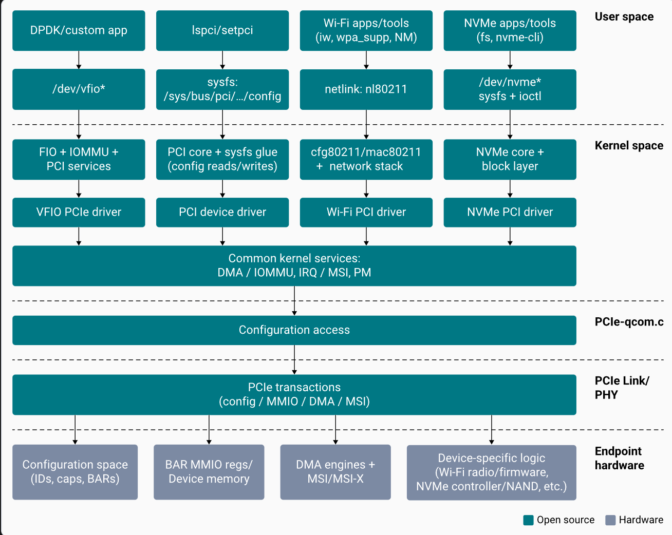
下图展示了 PCIe 软件架构。

<Frame>
  <img src="https://mintcdn.com/qualcomm-staging/uWQLnBcS9sxlZhgB/System/Interfaces/images/pcie_software_architecture.png?fit=max&auto=format&n=uWQLnBcS9sxlZhgB&q=85&s=51a7f32b541989bca88be0a272005734" alt="PCIe 软件架构" width="1308" height="1042" data-path="System/Interfaces/images/pcie_software_architecture.png" />
</Frame>

<p align="center"><strong>图：PCIe 软件架构</strong></p>

下图展示了 PCIe 的分层架构模型。

<Frame>
  <img src="https://mintcdn.com/qualcomm-staging/uWQLnBcS9sxlZhgB/System/Interfaces/images/pcie-architecture.svg?fit=max&auto=format&n=uWQLnBcS9sxlZhgB&q=85&s=99c14e6b8f897655f1e4a6cbc4bebe4e" alt="PCIe 分层架构" width="750" height="814" data-path="System/Interfaces/images/pcie-architecture.svg" />
</Frame>

<p align="center"><strong>图：PCIe 分层架构</strong></p>

交换的传输单元如下。

* 物理层实体之间的有序集（Ordered set）。
* 数据链路层实体之间的数据链路层数据包（DLLP）。
* 事务层实体之间的事务层数据包（TLP）。

下表列出了 PCIe 架构中的三个层及其各自的功能。

<p align="center"><strong>表：PCIe 架构中的层</strong></p>

<div style={{ overflowX: "auto", width: "100%" }}>
  <table
    style={{
  borderCollapse: "collapse",
  border: "1px solid #444",
  tableLayout: "auto",
  width: "max-content",
}}
  >
    <thead>
      <tr style={{ backgroundColor: "#4a4a4a" }}>
        <th
          style={{
        border: "1px solid #555",
        padding: "10px",
        textAlign: "center",
        whiteSpace: "nowrap",
        minWidth: "220px",
      }}
        >
          层
        </th>

        <th
          style={{
        border: "1px solid #555",
        padding: "10px",
        textAlign: "center",
        whiteSpace: "nowrap",
        minWidth: "900px",
      }}
        >
          特性
        </th>
      </tr>
    </thead>

    <tbody>
      <tr>
        <td
          rowSpan="2"
          style={{
        border: "1px solid #555",
        padding: "10px",
        verticalAlign: "top",
        fontWeight: "bold",
        whiteSpace: "nowrap",
      }}
        >
          物理层
        </td>

        <td style={{ border: "1px solid #555", padding: "10px", whiteSpace: "nowrap" }}>
          逻辑子块：链路训练、初始化和维护。
        </td>
      </tr>

      <tr>
        <td style={{ border: "1px solid #555", padding: "10px", whiteSpace: "nowrap" }}>
          物理子块：8b/10b 编码和解码，以及并串和串并转换。
        </td>
      </tr>

      <tr>
        <td
          rowSpan="3"
          style={{
        border: "1px solid #555",
        padding: "10px",
        verticalAlign: "top",
        fontWeight: "bold",
        whiteSpace: "nowrap",
      }}
        >
          数据链路层
        </td>

        <td style={{ border: "1px solid #555", padding: "10px", whiteSpace: "nowrap" }}>
          DLLP 数据包的组装和拆卸。
        </td>
      </tr>

      <tr>
        <td style={{ border: "1px solid #555", padding: "10px", whiteSpace: "nowrap" }}>
          链路层 CRC（LCRC）的生成和验证。
        </td>
      </tr>

      <tr>
        <td style={{ border: "1px solid #555", padding: "10px", whiteSpace: "nowrap" }}>
          确认和否定确认协议（重传出错的 TLP）。
        </td>
      </tr>

      <tr>
        <td
          rowSpan="5"
          style={{
        border: "1px solid #555",
        padding: "10px",
        verticalAlign: "top",
        fontWeight: "bold",
        whiteSpace: "nowrap",
      }}
        >
          事务层
        </td>

        <td style={{ border: "1px solid #555", padding: "10px", whiteSpace: "nowrap" }}>
          TLP 数据包的组装和拆卸。
        </td>
      </tr>

      <tr>
        <td style={{ border: "1px solid #555", padding: "10px", whiteSpace: "nowrap" }}>
          端到端 CRC（ECRC）的生成和验证。
        </td>
      </tr>

      <tr>
        <td style={{ border: "1px solid #555", padding: "10px", whiteSpace: "nowrap" }}>
          流量控制：接收实体使用 DLLP 通告可用接收缓冲区大小信息。
        </td>
      </tr>

      <tr>
        <td style={{ border: "1px solid #555", padding: "10px", whiteSpace: "nowrap" }}>
          服务质量（QoS）：流量类别（TC）到虚拟通道（VC）的映射。
        </td>
      </tr>

      <tr>
        <td style={{ border: "1px solid #555", padding: "10px", whiteSpace: "nowrap" }}>
          事务排序：在 VC 内实现事务排序规则。
        </td>
      </tr>
    </tbody>
  </table>
</div>

PCI 为每个功能定义了一个专用的配置地址空间块，如下图所示。软件确定功能的存在、对其进行配置，并检查和控制其状态。

<Frame>
  <img src="https://mintcdn.com/qualcomm-staging/uWQLnBcS9sxlZhgB/System/Interfaces/images/pcie-compatible-configuration-space.svg?fit=max&auto=format&n=uWQLnBcS9sxlZhgB&q=85&s=b836f9b540854dbd64413a86c122b200" alt="PCIe 配置地址空间" width="1220" height="1164" data-path="System/Interfaces/images/pcie-compatible-configuration-space.svg" />
</Frame>

<p align="center"><strong>图：PCIe 配置地址空间</strong></p>

## **PCIe 软件驱动程序配置**

PCIe 控制器驱动程序初始化 PCIe 资源并执行链路训练。训练成功后，控制器驱动程序调用 PCIe 框架进行链路枚举，例如端点发现、识别客户端驱动程序并探测这些驱动程序。有关 PCIe 框架和客户端驱动程序 PCIe 注册的更多信息，请参阅 [https://www.kernel.org/doc/html/latest/PCI/index.html](https://www.kernel.org/doc/html/latest/PCI/index.html)。

### **链路训练**

链路训练包括以下操作：

1. 位于 [https://github.com/torvalds/linux/blob/master/drivers/pci/controller/dwc/pcie-qcom.c](https://github.com/torvalds/linux/blob/master/drivers/pci/controller/dwc/pcie-qcom.c) 的 PCIe 驱动程序 `pcie-qcom.c` 文件从设备树获取所需资源，例如稳压器、时钟。
2. PCIe 驱动程序调用位于 [https://github.com/torvalds/linux/blob/master/drivers/pci/controller/dwc/pcie-designware-host.c](https://github.com/torvalds/linux/blob/master/drivers/pci/controller/dwc/pcie-designware-host.c) 的 Synopsys DesignWare® Core 主机驱动程序 *pcie-designware-host.c* 文件来初始化根复合体。
3. Synopsys DesignWare Core 驱动程序执行所有必要的初始化。
4. Synopsys DesignWare Core 驱动程序调用函数指针以执行主机初始化。
5. Qualcomm PCIe 驱动程序执行 PHY 上电，启用所有稳压器、时钟。
6. Synopsys DesignWare Core 驱动程序通过调用启动链路的函数指针来开始链路训练。

### **硬件初始化**

驱动程序初始化并配置 PCIe 硬件模块并执行链路训练。初始化在调用 `platform _probe()` 驱动函数之后进行。

```bash theme={null}
static int qcom_pcie_probe(struct platform_device *pdev)
{

        // get PCIe resources

        ret = dw_pcie_host_init(pp);  // call DWC framework to host intialisation like MSI, MSIx and controller init 
        if (ret) {
                dev_err(dev, "cannot initialize host\n");
                goto err_phy_exit;
        }

};

static const struct of_device_id qcom_pcie_match[] = {
        { .compatible = "qcom,pcie-sc7280", .data = &cfg_1_9_0 },
        {}

};

static struct platform_driver qcom_pcie_driver = {
        .probe = qcom_pcie_probe,
        .driver = {
                .name = "qcom-pcie",
                .suppress_bind_attrs = true,
                .of_match_table = qcom_pcie_match,
        },
};
```

当 Synopsys DesignWare Core 驱动程序初始化时，它还会初始化 MSI、MSIx 和控制器。该驱动程序调用 Qualcomm 函数指针以开始链路训练。

```bash theme={null}
static int qcom_pcie_start_link(struct dw_pcie *pci)
{
        struct qcom_pcie *pcie = to_qcom_pcie(pci);

        /* Enable Link Training state machine */
        if (pcie->cfg->ops->ltssm_enable)
                pcie->cfg->ops->ltssm_enable(pcie);

        return 0;
}

static int qcom_pcie_link_up(struct dw_pcie *pci)
{
        u16 offset = dw_pcie_find_capability(pci, PCI_CAP_ID_EXP);
        u16 val = readw(pci->dbi_base + offset + PCI_EXP_LNKSTA);

        return !!(val & PCI_EXP_LNKSTA_DLLLA); // checks the link is up or not
}
static const struct dw_pcie_ops dw_pcie_ops = {
        .link_up = qcom_pcie_link_up,
        .start_link = qcom_pcie_start_link,
};
```

Synopsys DesignWare Core 驱动程序等待链路激活后再枚举 PCI 框架。Qualcomm PCIe 驱动程序仅启用链路训练。

<Note>
  注意：PCIE\_0 根复合体实例默认启用，用于 WLAN EP 连接。
</Note>

## 为 Dragonwing IQ-9075（Lemans）启用 PCIe 端点（EP）模式

Dragonwing IQ-9075（Lemans）上的每个 PCIe 控制器实例都可以运行在根复合体（RC）或端点（EP）模式，但不能同时运行两种模式。设备树在同一基地址处为每种模式定义了单独的节点,并且每个 PCIe 实例每次只能启用其中一个。

<Note>
  注意：Monaco 也支持 PCIe EP 模式，但该支持尚未包含在当前内核代码树中，计划在后续版本中提供。
</Note>

<p align="center"><strong>表：Lemans PCIe EP 节点</strong></p>

<table
  style={{
width: "100%",
borderCollapse: "collapse",
border: "1px solid #444",
}}
>
  <thead>
    <tr style={{ backgroundColor: "#3a3a3a" }}>
      <th style={{ border: "1px solid #555", padding: "10px", textAlign: "center", whiteSpace: "nowrap" }}>EP 节点</th>
      <th style={{ border: "1px solid #555", padding: "10px", textAlign: "center", whiteSpace: "nowrap" }}>RC 节点（互斥）</th>
      <th style={{ border: "1px solid #555", padding: "10px", textAlign: "center", whiteSpace: "nowrap" }}>Compatible</th>
      <th style={{ border: "1px solid #555", padding: "10px", textAlign: "center", whiteSpace: "nowrap" }}>num-lanes</th>
      <th style={{ border: "1px solid #555", padding: "10px", textAlign: "center", whiteSpace: "nowrap" }}>linux,pci-domain</th>
    </tr>
  </thead>

  <tbody>
    <tr>
      <td style={{ border: "1px solid #555", padding: "10px", textAlign: "center", whiteSpace: "nowrap" }}>pcie0\_ep</td>
      <td style={{ border: "1px solid #555", padding: "10px", textAlign: "center", whiteSpace: "nowrap" }}>pcie0</td>
      <td style={{ border: "1px solid #555", padding: "10px", textAlign: "center", whiteSpace: "nowrap" }}>qcom,sa8775p-pcie-ep</td>
      <td style={{ border: "1px solid #555", padding: "10px", textAlign: "center", whiteSpace: "nowrap" }}>2</td>
      <td style={{ border: "1px solid #555", padding: "10px", textAlign: "center", whiteSpace: "nowrap" }}>0</td>
    </tr>

    <tr>
      <td style={{ border: "1px solid #555", padding: "10px", textAlign: "center", whiteSpace: "nowrap" }}>pcie1\_ep</td>
      <td style={{ border: "1px solid #555", padding: "10px", textAlign: "center", whiteSpace: "nowrap" }}>pcie1</td>
      <td style={{ border: "1px solid #555", padding: "10px", textAlign: "center", whiteSpace: "nowrap" }}>qcom,sa8775p-pcie-ep</td>
      <td style={{ border: "1px solid #555", padding: "10px", textAlign: "center", whiteSpace: "nowrap" }}>4</td>
      <td style={{ border: "1px solid #555", padding: "10px", textAlign: "center", whiteSpace: "nowrap" }}>1</td>
    </tr>
  </tbody>
</table>

`pcie0_ep` 和 `pcie1_ep` 均在 `arch/arm64/boot/dts/qcom/lemans.dtsi` 中定义，且默认 `status = "disabled"`,因为对应的 RC 节点(`pcie0`、`pcie1`)已启用。绑定到这些节点的 Qualcomm PCIe EP 控制器驱动程序为 `drivers/pci/controller/dwc/pcie-qcom-ep.c`(驱动名称 `qcom-pcie-ep`)。

### **PCIe EP 模式内核配置**

`CONFIG_PCI_ENDPOINT` 和 `CONFIG_PCI_ENDPOINT_CONFIGFS` 已在 Lemans defconfig 中启用。用于构建 Qualcomm EP 控制器驱动程序的 `CONFIG_PCIE_QCOM_EP` 默认未启用，必须开启才能启用 EP 模式。`CONFIG_PCI_EPF_MHI` 及其依赖项 `CONFIG_MHI_BUS_EP` 也默认未启用，必须开启才能使用 MHI 端点功能。

要启用这些配置，请将以下补丁应用到 *arch/arm64/configs/defconfig* 文件。

```bash theme={null}
QCLINUX: arm64: defconfig: qcom:
diff --git a/arch/arm64/configs/defconfig b/arch/arm64/configs/defconfig
index 7293680..730122c 100644
--- a/arch/arm64/configs/defconfig
+++ b/arch/arm64/configs/defconfig
@@ -242,6 +242,7 @@
 CONFIG_PCIE_QCOM=y
+CONFIG_PCIE_QCOM_EP=y
 CONFIG_PCI_ENDPOINT=y
 CONFIG_PCI_ENDPOINT_CONFIGFS=y
 CONFIG_PCI_EPF_TEST=m
+CONFIG_PCI_EPF_MHI=m
+CONFIG_MHI_BUS_EP=m
```

<Note>
  注意：`CONFIG_PCIE_QCOM_EP` 依赖 `CONFIG_PCI_ENDPOINT`,并选择 `drivers/pci/controller/dwc/Kconfig` 中定义的 `CONFIG_PCIE_DW_EP` 和 `CONFIG_PCIE_QCOM_COMMON`。`CONFIG_PCI_EPF_MHI` 定义于 `drivers/pci/endpoint/functions/Kconfig`,依赖 `CONFIG_MHI_BUS_EP`——即 `drivers/bus/mhi/ep/Kconfig` 中的 MHI 端点总线实现。
</Note>

### **在设备树中启用 EP 节点**

`pcie1`（RC）和 `pcie1_ep`（EP）都在 `lemans.dtsi` 中通过标签定义，且 `pcie1` 在其中默认 `status = "disabled"`。然而，`lemans-evk.dts` 又通过板载 M.2 E-key 连接器将 `pcie1` 重新启用为 RC 模式(`&pcie1 { ... status = "okay"; };`)。由于每个 PCIe 实例在同一时间只能处于 RC 或 EP 中的一种模式，因此在 Lemans EVK 上将 `PCIE_1` 切换为 EP 模式意味着禁用该 RC 覆盖，并改为启用 `pcie1_ep`。将以下更改应用到 `arch/arm64/boot/dts/qcom/lemans-evk.dts`：

```bash theme={null}
diff --git a/arch/arm64/boot/dts/qcom/lemans-evk.dts b/arch/arm64/boot/dts/qcom/lemans-evk.dts
--- a/arch/arm64/boot/dts/qcom/lemans-evk.dts
+++ b/arch/arm64/boot/dts/qcom/lemans-evk.dts
@@ -856,13 +856,14 @@
 };
 
 &pcie1 {
-	perst-gpios = <&tlmm 4 GPIO_ACTIVE_LOW>;
-	wake-gpios = <&tlmm 5 GPIO_ACTIVE_HIGH>;
+	status = "disabled";
+};
 
-	pinctrl-0 = <&pcie1_default_state>;
+&pcie1_ep {
+	reset-gpios = <&tlmm 4 GPIO_ACTIVE_LOW>;
+	wake-gpios = <&tlmm 5 GPIO_ACTIVE_HIGH>;
+	pinctrl-0 = <&pcie1_default_state>;
 	pinctrl-names = "default";
 
 	status = "okay";
 };
```

`pcie1_default_state`（在 `lemans-evk.dts` 靠后位置的 `&tlmm` 节点中定义）为 GPIO 4 (PERST#) 和 GPIO 5 (WAKE#) 设置了引脚功能、驱动强度和偏置，但没有固定它们的方向,因此 EP 节点可以复用与 RC 模式相同的 pinctrl 组和物理 GPIO。但是,每个 GPIO 上的信号方向会在两种模式之间反转:

* 在 RC 模式下,`pcie-qcom.c` 将 PERST# GPIO 请求为 `GPIOD_OUT_HIGH`——根复合体驱动 PERST# 以复位下行设备。RC 模式不驱动 WAKE# GPIO。
* 在 EP 模式下,`pcie-qcom-ep.c` 将 `reset-gpios` 请求为 `GPIOD_IN`——端点将 PERST# 作为输入读取,由连接的根复合体驱动;并将 `wake-gpios` 请求为 `GPIOD_OUT_LOW`——端点将 WAKE# 作为输出驱动到主机。

GPIO 方向由驱动程序在 probe 时根据其匹配的模式绑定设置,而不是由 pinctrl 组设置,因此不需要为方向切换额外修改设备树。

<Note>
  注意：上游 `qcom,pcie-ep.yaml` 绑定要求提供 `reset-gpios`,即连接到由所连接根复合体驱动的 PERST# 输入的 GPIO。`lemans.dtsi` 中的 `pcie1_ep` 节点没有定义该属性,因为它是板卡相关的。
</Note>

同样的步骤也适用于 `PCIE_0`：禁用 `pcie0` RC 覆盖，改为启用 `pcie0_ep`,复用 `pcie0_default_state` pinctrl 组及其 PERST#/WAKE# GPIO。

<Note>
  注意：禁用 `pcie0` 也会同时禁用 M.2 E-key 连接器的 PCIe 链路(`pcieport0`)，因为该连接器在 RC 模式下接线到 `PCIE_0`。仅当你不需要将 M.2 连接器用于 PCIe 卡时，才将 `PCIE_0` 切换到 EP 模式。
</Note>

`phys`、`iommus`、`interconnects`、`power-domains`、`clocks` 和 `resets` 已在两个 EP 节点中填充完毕，标准 bring-up 时无需修改。

### **PCIe EP 驱动初始化**

`pcie-qcom-ep.c` 中的 `qcom_pcie_ep_probe()` 会获取 `parf`、`dbi`、`mmio` 和 `dma` 寄存器区域、全部五个实例时钟、`core` 复位、`reset`(PERST#)和可选的 `wake`(WAKE#) GPIO,以及可选的 `pciephy` PHY,然后调用公共的 DesignWare `dw_pcie_ep_init()` 来初始化端点核心。Lemans 匹配 `qcom,sa8775p-pcie-ep` compatible 字符串,该字符串选择 `cfg_1_34_0` 配置(启用 HDMA 支持、`NO_SNOOP` 覆盖,并禁用 MHI RAM 奇偶校验)。

一个全局 IRQ 线程(`qcom_pcie_ep_global_irq_thread()`)用于处理由连接的根复合体触发的链路建立/断开事件、总线主控使能(BME),以及 PM turn-off/D 状态通知。

### **使用 configfs 绑定 MHI 端点功能**

`pci-epf-mhi.c` 驱动在 `pci_epf_mhi_ids[]` 中为每个 SoC 注册一个设备 ID,每个都有各自的 header(vendor/device ID)和 MHI 通道配置。Lemans 匹配 `pci_epf_mhi_sa8775p` 条目,该条目设置设备 ID `0x0116`,使用 `BAR_0`、32 个 MSI 向量、MRU 为 `0x8000`,并启用 DMA 辅助传输(`MHI_EPF_USE_DMA`)。该条目还选择标准的 `mhi_v1_channels` 表(LOOPBACK、SAHARA、DIAG、SSR、QDSS、EFS、MBIM、QMI、IP-CTRL-1、IPCR、DUN、IP\_SW0)。header 和通道配置由此条目固定,因此无需通过 configfs 写入 `vendorid`/`deviceid`。

内核在启用 `pcie1_ep` 的情况下启动后,使用 PCI 端点 configfs 接口将 MHI 端点功能绑定到 `qcom-pcie-ep` 控制器。functions 目录名称必须与 `pci_epf_mhi_sa8775p` 条目匹配,以便探测到正确的设备 ID 和通道表。

```bash theme={null}
mount -t configfs none /sys/kernel/config
mkdir -p /sys/kernel/config/pci_ep/functions/pci_epf_mhi_sa8775p/func1

ln -s /sys/kernel/config/pci_ep/functions/pci_epf_mhi_sa8775p/func1 \
      /sys/kernel/config/pci_ep/controllers/1c10000.pcie-ep/

echo 1 > /sys/kernel/config/pci_ep/controllers/1c10000.pcie-ep/start
```

向 `start` 写入 `1` 会声明端点已就绪,允许链路与连接的根复合体进行训练。`pci_epf_mhi_bind()` 会从父 `qcom-pcie-ep` 平台设备中查找 `mmio` 寄存器区域和 `doorbell` 中断,而 `pci_epf_mhi_link_up()` 会在链路建立后注册 MHI 端点控制器。

<Note>
  注意：如果 `mhi_bus_ep` 和 `pci_epf_mhi` 构建为独立模块,请先加载 `mhi_bus_ep`,因为 `CONFIG_PCI_EPF_MHI` 依赖 `CONFIG_MHI_BUS_EP`。
</Note>

### **验证 MHI EP 模式枚举**

在连接到 Lemans EP 端口的主机上,确认设备已作为具有该 MHI 设备 ID 的 PCI 端点被枚举。

```text theme={null}
lspci -d 17cb:0116
```

输出:

```text theme={null}
0001:01:00.0 Unassigned class [ff00]: Qualcomm Device 0116
```

在目标端,确认 MHI 端点通道已注册。

```text theme={null}
cat /sys/bus/mhi_ep/devices/*/channels
```

有关基于 configfs 的端点 bring-up 流程的更多信息,请参阅 [https://www.kernel.org/doc/html/latest/PCI/endpoint/pci-endpoint-cfs.html](https://www.kernel.org/doc/html/latest/PCI/endpoint/pci-endpoint-cfs.html)。

## 启用 QPS615 PCIe 交换机

本节介绍如何在 Qualcomm Linux 硬件 SoC 中启用 QPS615 PCIe 交换机。QPS615 交换机端点在 `PCIe1` 实例上受支持。下图展示了 QPS615 端点和连接。

<Frame>
  <img src="https://mintcdn.com/qualcomm-staging/uWQLnBcS9sxlZhgB/System/Interfaces/images/qps615-pcie-switch.svg?fit=max&auto=format&n=uWQLnBcS9sxlZhgB&q=85&s=bea8b08a1861e62a73cf3833ff668ed4" alt="QPS615 PCIe 交换机连接图" width="724" height="608" data-path="System/Interfaces/images/qps615-pcie-switch.svg" />
</Frame>

<p align="center"><strong>图：QPS615 PCIe 交换机连接图</strong></p>

可从以下位置访问 Qualcomm PCIe 驱动程序文档：

* [https://github.com/torvalds/linux/blob/master/Documentation/devicetree/bindings/pci/qcom%2Cpcie-sc8280xp.yaml](https://github.com/torvalds/linux/blob/master/Documentation/devicetree/bindings/pci/qcom%2Cpcie-sc8280xp.yaml)
* [https://elixir.bootlin.com/linux/v6.6.48/source/Documentation/devicetree/bindings/pci/qcom,pcie.yaml](https://elixir.bootlin.com/linux/v6.6.48/source/Documentation/devicetree/bindings/pci/qcom,pcie.yaml)
* [https://github.com/torvalds/linux/blob/master/Documentation/devicetree/bindings/phy/qcom%2Csc8280xp-qmp-pcie-phy.yaml](https://github.com/torvalds/linux/blob/master/Documentation/devicetree/bindings/phy/qcom%2Csc8280xp-qmp-pcie-phy.yaml)

### **PCIe 相关配置**

以下配置默认启用，以支持 QPS615 交换机。若要将其用于其他 PCIe 端点，请通过还原代码更改来禁用 QPS615 交换机的默认支持。

要启用 PCIe 相关的 `configs`，请将以下补丁应用到 */arch/arm64/configs/qcom\_addons.config* 文件。

```bash theme={null}
QCLINUX: arm64: defconfig: qcom:
diff --git a/arch/arm64/configs/qcom_defconfig b/arch/arm64/configs/qcom_defconfig
index 7293680..730122c 100644
--- a/arch/arm64/configs/qcom_defconfig
+++ b/arch/arm64/configs/qcom_defconfig
@@ -173,6 +173,7 @@
 CONFIG_HOTPLUG_PCI=y
 CONFIG_HOTPLUG_PCI_ACPI=y
 CONFIG_PCI_HOST_GENERIC=y
+CONFIG_PCIE_DW_PLAT_HOST=y
 CONFIG_PCIE_QCOM=y
 CONFIG_PCI_ENDPOINT=y
 CONFIG_PCI_ENDPOINT_CONFIGFS=y
@@ -793,3 +794,5 @@
 CONFIG_CORESIGHT_TPDM=m
 CONFIG_CORESIGHT_DUMMY=m
 CONFIG_MEMTEST=y
+CONFIG_PCIEASPM=y
+CONFIG_PCIEASPM_POWER_SUPERSAVE=y
```

### **消息信号中断（MSI）**

当前的 MSI 映射并不包含所有向量。Qualcomm Linux 硬件 SoC 支持八个向量。每个向量又支持 32 个 MSI。因此，支持的 MSI 总数为 256。

有关为此 PCIe 实例添加所有受支持的 MSI 组的信息，请参阅 [https://lore.kernel.org/linux-arm-msm/f1168212-bc6e-4570-869c-2870d6f248ad@linaro.org/T/](https://lore.kernel.org/linux-arm-msm/f1168212-bc6e-4570-869c-2870d6f248ad@linaro.org/T/)。

### **PCIe 内核驱动程序日志示例**

以下是来自 QPS615 设备枚举的 PCIe 内核驱动程序日志示例。

<div
  style={{
maxHeight: "260px",
overflowY: "auto",
overflowX: "auto",
border: "1px solid #444",
borderRadius: "8px",
}}
>
  <pre style={{ margin: 0, padding: "12px", whiteSpace: "pre" }}>
    {`[    7.254674] qcom-pcie 1c08000.pci: supply vdda not found, using dummy regulator
        [    7.285224] qcom-pcie 1c08000.pci: supply vddpe-3v3 not found, using dummy regulator
        [    7.299688] qcom-pcie 1c08000.pci: host bridge /soc@0/pci@1c08000 ranges:
        [    7.313713] qcom-pcie 1c08000.pci: IO 0x0040200000..0x00402fffff -> 0x0000000000
        [    7.329778] qcom-pcie 1c08000.pci: MEM 0x0040300000..0x005fffffff -> 0x0040300000
        [    7.479174] qcom-pcie 1c08000.pci: iATU: unroll T, 8 ob, 8 ib, align 4K, limit 1024G
        [    7.577792] qcom-pcie 1c08000.pci: PCIe Gen.3 x2 link up
        [    7.648353] qcom-pcie 1c08000.pci: PCI host bridge to bus 0001:00
        [    7.654618] pci_bus 0001:00: root bus resource [bus 00-ff]
        [    7.654620] pci_bus 0001:00: root bus resource [io  0x0000-0xfffff]
        [    7.654622] pci_bus 0001:00: root bus resource [mem 0x40300000-0x5fffffff]
        [    7.654633] pci 0001:00:00.0: [17cb:010b] type 01 class 0x060400
        [    7.665893] pci 0001:00:00.0: reg 0x10: [mem 0x00000000-0x00000fff]
        [    7.684913] pci 0001:00:00.0: PME# supported from D0 D3hot D3cold
        [    7.700502] pci 0001:01:00.0: [1179:0623] type 01 class 0x060400
        [    7.710817] pci 0001:01:00.0: PME# supported from D0 D3hot D3cold
        [    7.733698] pci 0001:01:00.0: bridge configuration invalid ([bus 00-00]), reconfiguring
        [    7.738818] pci 0001:02:01.0: [1179:0623] type 01 class 0x060400
        [    7.751157] pci 0001:02:01.0: PME# supported from D0 D3hot D3cold
        [    7.763174] pci 0001:02:02.0: [1179:0623] type 01 class 0x060400
        [    7.777084] pci 0001:02:02.0: PME# supported from D0 D3hot D3cold
        [    7.792832] pci 0001:02:03.0: [1179:0623] type 01 class 0x060400
        [    7.815659] pci 0001:02:03.0: PME# supported from D0 D3hot D3cold`}
  </pre>
</div>

## **通过 QPS615 PCIe 交换机支持的以太网接口**

QPS615 PCIe 交换机为设备启用以太网连接。当设备加载 QPS615 驱动程序并建立 PCIe 链路时，默认情况下会在设备启动期间自动激活受支持的以太网接口。

要自定义默认配置或启用 Qualcomm 硬件设置之外的额外 MAC/PHY 组件，请参阅 [*Qualcomm Linux Ethernet guide*](https://docs.qualcomm.com/bundle/publicresource/topics/80-80021-26/bring_up-ethernet.html) 中的 *Bring up Ethernet* 部分。

<p align="center"><strong>表：支持的以太网接口</strong></p>

<div style={{ overflowX: "auto" }}>
  <table
    style={{
  borderCollapse: "collapse",
  border: "1px solid #444",
  width: "max-content",
}}
  >
    <thead>
      <tr style={{ backgroundColor: "#4a4a4a" }}>
        <th style={{ border: "1px solid #555", padding: "10px", whiteSpace: "nowrap" }}>
          接口类型
        </th>

        <th style={{ border: "1px solid #555", padding: "10px", whiteSpace: "nowrap" }}>
          速度
        </th>

        <th style={{ border: "1px solid #555", padding: "10px", whiteSpace: "nowrap" }}>
          连接器类型
        </th>

        <th style={{ border: "1px solid #555", padding: "10px", whiteSpace: "nowrap", minWidth: "420px" }}>
          说明
        </th>
      </tr>
    </thead>

    <tbody>
      <tr>
        <td style={{ border: "1px solid #555", padding: "10px", whiteSpace: "nowrap", fontWeight: "bold" }}>
          QEP PHY (SGMII)
        </td>

        <td style={{ border: "1px solid #555", padding: "10px", whiteSpace: "nowrap" }}>
          2.5 GbE
        </td>

        <td style={{ border: "1px solid #555", padding: "10px", whiteSpace: "nowrap" }}>
          IX/RJ45 连接器（QEP8121）
        </td>

        <td style={{ border: "1px solid #555", padding: "10px" }}>
          <ul style={{ margin: 0, paddingLeft: "18px" }}>
            <li>默认启用。</li>
          </ul>
        </td>
      </tr>

      <tr>
        <td style={{ border: "1px solid #555", padding: "10px", whiteSpace: "nowrap", fontWeight: "bold" }}>
          AQR PHY (USXGMII)
        </td>

        <td style={{ border: "1px solid #555", padding: "10px", whiteSpace: "nowrap" }}>
          10 GbE
        </td>

        <td style={{ border: "1px solid #555", padding: "10px", whiteSpace: "nowrap" }}>
          IX/RJ45 连接器（AQR113C）
        </td>

        <td style={{ border: "1px solid #555", padding: "10px" }}>
          <ul style={{ margin: 0, paddingLeft: "18px" }}>
            <li>
              10 千兆以太网 AQR PHY 是 RB3 Gen 2 开发套件以及
              Dragonwing IQ-8275 和 Dragonwing IQ-9075 评估套件（EVK）中的可选组件。
              它已在 AQR113C 上通过验证。
            </li>
          </ul>
        </td>
      </tr>
    </tbody>
  </table>
</div>

### **启用替代硬件组件**

您可以连接 Qualcomm 提供的硬件配置之外的 MAC/PHY 组件并将其启用。
要将 QPS615 替换为其他基于 PCIe 的 MAC/PHY，请参阅[启用 QPS615 PCIe 交换机](#enable-qps615-pcie-switch)。

<Note>
  注意：您必须从相应的供应商处获取 MAC/PHY 驱动程序和固件。Qualcomm 对这些配置更改不承担责任。
</Note>

## **通过 PCIe 交换机启用 USB 接口**

本节介绍如何在 Qualcomm Linux 硬件 SoC 中通过 PCIe 交换机激活 USB 接口。PCIE1 实例连接到 QPS615 交换机的端点，QPS615 的下游端口连接到 PCIe 转 USB 端点。有关使用 QPS615 的 PCIe 转 USB 端点连接，请参阅位于 [https://docs.qualcomm.com/bundle/publicresource/topics/80-80021-251/rb3\_hardware\_overview.html](https://docs.qualcomm.com/bundle/publicresource/topics/80-80021-251/rb3_hardware_overview.html) 的主板和转接板框图。

<Note>
  注意：Dragonwing IQ-9075 PCIe 软件不支持 USB。
</Note>

USB 集线器的电源通过 pwrctrl 驱动程序启用，有关这些详细信息，请参阅以下上游链接。

[https://elixir.bootlin.com/linux/v7.1/source/arch/arm64/boot/dts/qcom/qcs6490-rb3gen2.dts#L896](https://elixir.bootlin.com/linux/v7.1/source/arch/arm64/boot/dts/qcom/qcs6490-rb3gen2.dts#L896)
[https://elixir.bootlin.com/linux/v7.1/source/Documentation/devicetree/bindings/usb/renesas,upd720201-pci.yaml](https://elixir.bootlin.com/linux/v7.1/source/Documentation/devicetree/bindings/usb/renesas,upd720201-pci.yaml)
[https://elixir.bootlin.com/linux/v7.1/source/drivers/pci/pwrctrl/generic.c](https://elixir.bootlin.com/linux/v7.1/source/drivers/pci/pwrctrl/generic.c)

````

### **避免 PCIe 转 USB 控制器中的提前交接（early handoff）**

由于固件尚未加载，请确保对 PCIe 转 USB 控制器跳过 `usb_early-handoff`。此预防措施是必要的，以防止对启动时长产生不利影响。

```text
diff --git a/drivers/usb/host/pci-quirks.c b/drivers/usb/host/pci-quirks.c
index 2665832..c3d488f 100644
--- a/drivers/usb/host/pci-quirks.c
+++ b/drivers/usb/host/pci-quirks.c
@@ -1260,6 +1260,11 @@
 			return;
 	}
 
+	/* Skip handoff for Renesas PCI USB controller on QCOM SOC */
+	if ((pdev->vendor == PCI_VENDOR_ID_RENESAS) &&
+		(pcie_find_root_port(pdev)->vendor == PCI_VENDOR_ID_QCOM))
+		return;
+
 	if (pdev->class != PCI_CLASS_SERIAL_USB_UHCI &&
 			pdev->class != PCI_CLASS_SERIAL_USB_OHCI &&
 			pdev->class != PCI_CLASS_SERIAL_USB_EHCI &&
````

### **下载 PCIe 转 USB 控制器固件**

要从 [https://www.renesas.com/us/en/products/interface/usb-switches-hubs/upd720201-usb-30-host-controller#design\_development](https://www.renesas.com/us/en/products/interface/usb-switches-hubs/upd720201-usb-30-host-controller#design_development) 下载固件，请注册并登录 [https://www.renesas.com/](https://www.renesas.com/)。将下载的固件文件重命名为 *renesas\_usb\_fw\.mem*。

<Note>
  注意：为防止命令失败，请在更新 Renesas 固件之前，按照 [Set up the device](https://docs.qualcomm.com/bundle/publicresource/topics/80-80021-251/set_up_the_device.html) 部分中的说明更新软件。
</Note>

选项 1（Ubuntu）：使用 SCP 或类似工具推送固件文件。例如，

```text theme={null}
scp renesas_usb_fw.mem root@10.92.175.138:/lib/firmware
```

选项 2（Yocto）：

1. 通过 USB 线缆将设备连接到主机 PC 以使用 adb。
2. 将固件推送到设备。
   ```text theme={null}
   mount -o remount,rw /usr
   adb push renesas_usb_fw.mem /lib/firmware
   ```
3. 要激活固件，请执行以下任一选项。
   * 选项 A：重启目标设备以启用 USB Type-A 端口。
   * 选项 B：手动绑定 Renesas xHCI 驱动程序。
     ```text theme={null}
     echo "0001:04:00.0" > /sys/bus/pci/drivers/xhci-pci-renesas/bind
     ```
4. 验证固件枚举。
   ```text theme={null}
   dmesg
   ```

### **用于 PCIe 转 USB 设备枚举参考的 PCIe 内核驱动程序日志**

您可以运行以下命令来查看设备信息：

* 要显示 USB 中的设备信息，请运行以下命令。
  ```text theme={null}
  lsusb
  ```
  将显示以下消息。
  ```text theme={null}
  Bus 002 Device 003: ID 0b95:1790 ASIX Electronics Corp. AX88179 Gigabit Ethernet
  Bus 002 Device 002: ID 05e3:0625 Genesys Logic, Inc. USB3.2 Hub
  Bus 002 Device 001: ID 1d6b:0003 Linux Foundation 3.0 root hub
  Bus 001 Device 002: ID 05e3:0610 Genesys Logic, Inc. Hub
  Bus 001 Device 001: ID 1d6b:0002 Linux Foundation 2.0 root hub
  ```
* 要显示 PCIe 中的设备信息，请运行以下命令。
  ```text theme={null}
  lspci
  ```
  将显示以下消息。
  ```text theme={null}
  0001:00:00.0 PCI bridge: Qualcomm Device 010b
  0001:01:00.0 PCI bridge: Toshiba Corporation Device 0623
  0001:02:01.0 PCI bridge: Toshiba Corporation Device 0623
  0001:02:02.0 PCI bridge: Toshiba Corporation Device 0623
  0001:02:03.0 PCI bridge: Toshiba Corporation Device 0623
  0001:04:00.0 USB controller: Renesas Technology Corp. uPD720201 USB 3.0 Host Controller (rev 03)
  0001:05:00.0 Ethernet controller: Toshiba Corporation Device 0220
  0001:05:00.1 Ethernet controller: Toshiba Corporation Device 0220
  ```

## **级联连接 QPS615 交换机**

以级联方式连接 QPS615 交换机，以启用额外的以太网、PCIe 和 USB 端口。

<Note>
  注意：此功能仅在 QCS6490 中受支持。
</Note>

下图展示了以级联方式连接到 PCIE1 的两个 QPS615 交换机，以及连接到 PCIE2 的另一个 QPS615 交换机。

<Frame caption="图：QPS615 交换机级联连接">
  <img src="https://mintcdn.com/qualcomm-staging/uWQLnBcS9sxlZhgB/System/Interfaces/images/qps615-switches-cascade.svg?fit=max&auto=format&n=uWQLnBcS9sxlZhgB&q=85&s=7a44bc8916e80e18d020be38d015cf4b" alt="QPS615 级联连接" width="1268" height="596" data-path="System/Interfaces/images/qps615-switches-cascade.svg" />
</Frame>

要为所有端点启动链路训练和枚举，请执行以下操作：

1. 要重置 QPS615 交换机，请切换 QPS615 #1 和 QPS615 #2 的 RESX GPIO。
2. 要控制端点重置，请触发 PERST。两个交换机共享 PERST。

设备可以直接连接到 QPS615 交换机。PCIe RC0 连接到 WLAN 端点。由于 PCIe 节点层次结构，存在以下差异。

* 连接到交换机的设备：
  * QPS615 PCIe 树节点层次结构是静态固定的。
  * 用于交换 USP 和 DSP 端口的所有节点都在 PCIe 初始化期间创建。
  * 其中一个交换机 DSP 端口代表 WLAN。
  * 如果禁用 WLAN 节点，将禁用 WLAN 设备，但 PCIe 下游端口仍保持启用状态，并返回默认的最大链路宽度。
* 直接连接的 WLAN 设备：
  * 仅禁用单个节点。
  * 当 WLAN 被禁用时，返回 Invalid argument。

## **通过 PCIe 接口启用 NVMe**

本节介绍如何使用 PCIe 启用 NVMe 以进行存储扩展。要验证 NVMe 是否通过 PCIe 接口连接，请执行以下操作：

1. 要显示 PCIe 设备信息，请运行以下命令。
   ```text theme={null}
   lspci
   ```
   输出：
   ```text theme={null}
   0000:00:00.0 PCI bridge: Qualcomm Device 0115
   	0000:01:00.0 Network controller: Qualcomm QCNFA765 Wireless Network Adapter (rev 01)
   	0001:00:00.0 PCI bridge: Qualcomm Device 0115
   	0001:01:00.0 Non-Volatile memory controller: Samsung Electronics Co Ltd NVMe SSD Controller PM9A1/PM9A3/980PRO
   ```
2. 找到 PCIe 日志。
   ```text theme={null}
   dmesg | grep pcie
   ```
   输出：
   ```text theme={null}
   [    0.000000] Kernel command line:  root=/dev/disk/by-partlabel/system rw rootwait console=ttyMSM0,115200n8 
   pcie_pme=nomsi net.ifnames=0 pci=noaer kpti=off kasan=off kasan.stacktrace=off swiotlb=128 earlycon reboot=panic_warm page_owner=on qcom_scm.download_mode=1 slub_debug=FZP,
   zs_handle,zspage;FZPU mitigations=auto kernel.sched_pelt_multiplier=4 rcupdate.rcu_expedited=1 rcu_nocbs=0-7 no-steal-acc vfio_iommu_type1.allow_unsafe_interrupts=1 fw_devlink.strict=1
   	[    3.842071] qcom-pcie 1c00000.pci: supply vdda not found, using dummy regulator
   	[    3.845339] qcom-pcie 1c10000.pci: supply vdda not found, using dummy regulator
   	[    3.845428] qcom-pcie 1c10000.pci: supply vddpe-3v3 not found, using dummy regulator
   	[    3.845508] qcom-pcie 1c10000.pci: host bridge /pci@1c10000 ranges:
   	[    3.845519] qcom-pcie 1c10000.pci:       IO 0x0060200000..0x00602fffff -> 0x0000000000
   	[    3.845526] qcom-pcie 1c10000.pci:      MEM 0x0060300000..0x007fffffff -> 0x0060300000
   	[    3.848154] qcom-pcie 1c00000.pci: supply vddpe-3v3 not found, using dummy regulator
   	[    3.854556] qcom-pcie 1c00000.pci: host bridge /pci@1c00000 ranges:
   	[    3.860574] qcom-pcie 1c00000.pci:       IO 0x0040200000..0x00402fffff -> 0x0000000000
   	[    3.867362] qcom-pcie 1c00000.pci:      MEM 0x0040300000..0x005fffffff -> 0x0040300000
   	[    3.963275] qcom-pcie 1c10000.pci: iATU: unroll T, 32 ob, 8 ib, align 4K, limit 1024G
   	[    3.990385] qcom-pcie 1c00000.pci: iATU: unroll T, 32 ob, 8 ib, align 4K, limit 1024G
   	[    4.072091] qcom-pcie 1c10000.pci: PCIe Gen.4 x2 link up
   	[    4.080241] qcom-pcie 1c10000.pci: PCI host bridge to bus 0001:00
   	[    4.291824] pcieport 0001:00:00.0: Adding to iommu group 9
   	[    4.551677] pcieport 0001:00:00.0: PME: Signaling with IRQ 256
   	[    4.572484] WARNING: CPU: 3 PID: 89 at drivers/pci/controller/dwc/pcie-qcom.c:1430 qcom_pcie_icc_update+0xf8/0x144
   	[    4.595291] pc : qcom_pcie_icc_update+0xf8/0x144
   	[    4.595293] lr : qcom_pcie_icc_update+0x9c/0x144
   	[    4.640742]  qcom_pcie_icc_update+0xf8/0x144
   	[    4.640745]  qcom_pcie_probe+0x234/0x30c
   	[    4.988519] qcom-pcie 1c00000.pci: Phy link never came up
   	[    5.302179] qcom-pcie 1c00000.pci: PCI host bridge to bus 0000:00
   	[    5.372008] pcieport 0000:00:00.0: Adding to iommu group 10
   	[    5.378905] pcieport 0000:00:00.0: PME: Signaling with IRQ 257
   	[   11.564590] pcieport 0000:00:00.0: BAR 14: assigned [mem 0x40400000-0x405fffff]
   ```
3. 要找到 NVMe 目录，请运行以下命令。
   ```text theme={null}
   ls -lh /dev/nvme*
   ```
   输出：
   ```text theme={null}
   crw-------. 1 root root 508,  0 Jan  1 00:00 /dev/nvme0
   	brw-rw----. 1 root disk 259, 30 Jan  1 00:00 /dev/nvme0n1
   	
   ```

## **为 SMMUv2 目标更新 iommu-map 属性**

对使用 SMMUv2 IOMMU 处理 PCIe 的目标(例如 Dragonwing IQ-9075 (Lemans)、Monaco 和 Kodiak)而言,每个 PCIe Requester ID (RID) 都会通过 PCIe host bridge 节点中的 `iommu-map` 属性转换为一个 Stream ID (SID)。在给 PCIe 根复合体下游添加设备、交换机或端点时,此属性配置错误是导致出现 `no iommu-map translation for id` 失败的常见原因。

### **iommu-map 的工作原理**

每个 `iommu-map` 条目具有以下形式：

```text theme={null}
iommu-map = <rid_base  &smmu_phandle  sid_base  count>;
```

内核(`drivers/of/base.c: of_map_id()`)按以下规则处理:

```text theme={null}
if RID is in [rid_base, rid_base + count):
    SID = RID - rid_base + sid_base
```

多个条目按顺序检查,首个匹配项生效。当 `count = 1` 时,映射简化为 `RID == rid_base -> SID = sid_base`。每个条目使用 `count = 1`（稀疏点映射）可将一个 RID 精确固定到一个 SID,无论 RID 值有多大,并可避免耗尽 SMMU 实现的 SID 范围。

<Note>
  注意：简单的单一 range 条目,例如 `iommu-map = <0x0 &pcie_smmu 0x0000 0x500>;`,会将 `count` 个连续的 RID 映射到 `count` 个连续的 SID,因此 SID 偏移会随 RID 值成比例增长。一旦来自下游交换机或额外端点的 RID 超出 SMMU 可用的 SID 范围,这种映射就会失败。
</Note>

### **PCIe RID 与 SID 基础**

PCIe RID 是一个 16 位值,编码了总线、设备和功能：

```text theme={null}
RID = (Bus << 8) | (Device << 3) | Function
```

<p align="center"><strong>表：常见 RID 值</strong></p>

<div style={{ overflowX: "auto" }}>
  <table
    style={{
  borderCollapse: "collapse",
  border: "1px solid #444",
  width: "max-content",
}}
  >
    <thead>
      <tr style={{ backgroundColor: "#4a4a4a" }}>
        <th style={{ border: "1px solid #555", padding: "10px", whiteSpace: "nowrap" }}>Bus</th>
        <th style={{ border: "1px solid #555", padding: "10px", whiteSpace: "nowrap" }}>Dev</th>
        <th style={{ border: "1px solid #555", padding: "10px", whiteSpace: "nowrap" }}>Fn</th>
        <th style={{ border: "1px solid #555", padding: "10px", whiteSpace: "nowrap" }}>RID (hex)</th>
        <th style={{ border: "1px solid #555", padding: "10px", whiteSpace: "nowrap" }}>说明</th>
      </tr>
    </thead>

    <tbody>
      <tr>
        <td style={{ border: "1px solid #555", padding: "10px", textAlign: "center", whiteSpace: "nowrap" }}>0</td>
        <td style={{ border: "1px solid #555", padding: "10px", textAlign: "center", whiteSpace: "nowrap" }}>0</td>
        <td style={{ border: "1px solid #555", padding: "10px", textAlign: "center", whiteSpace: "nowrap" }}>0</td>
        <td style={{ border: "1px solid #555", padding: "10px", textAlign: "center", whiteSpace: "nowrap" }}>0x0000</td>
        <td style={{ border: "1px solid #555", padding: "10px", whiteSpace: "nowrap" }}>根复合体，始终存在</td>
      </tr>

      <tr>
        <td style={{ border: "1px solid #555", padding: "10px", textAlign: "center", whiteSpace: "nowrap" }}>1</td>
        <td style={{ border: "1px solid #555", padding: "10px", textAlign: "center", whiteSpace: "nowrap" }}>0</td>
        <td style={{ border: "1px solid #555", padding: "10px", textAlign: "center", whiteSpace: "nowrap" }}>0</td>
        <td style={{ border: "1px solid #555", padding: "10px", textAlign: "center", whiteSpace: "nowrap" }}>0x0100</td>
        <td style={{ border: "1px solid #555", padding: "10px", whiteSpace: "nowrap" }}>RC 下行的第一个设备（端点或交换机上行）</td>
      </tr>

      <tr>
        <td style={{ border: "1px solid #555", padding: "10px", textAlign: "center", whiteSpace: "nowrap" }}>2</td>
        <td style={{ border: "1px solid #555", padding: "10px", textAlign: "center", whiteSpace: "nowrap" }}>1</td>
        <td style={{ border: "1px solid #555", padding: "10px", textAlign: "center", whiteSpace: "nowrap" }}>0</td>
        <td style={{ border: "1px solid #555", padding: "10px", textAlign: "center", whiteSpace: "nowrap" }}>0x0208</td>
        <td style={{ border: "1px solid #555", padding: "10px", whiteSpace: "nowrap" }}>交换机下行端口，设备 1</td>
      </tr>

      <tr>
        <td style={{ border: "1px solid #555", padding: "10px", textAlign: "center", whiteSpace: "nowrap" }}>2</td>
        <td style={{ border: "1px solid #555", padding: "10px", textAlign: "center", whiteSpace: "nowrap" }}>16</td>
        <td style={{ border: "1px solid #555", padding: "10px", textAlign: "center", whiteSpace: "nowrap" }}>1</td>
        <td style={{ border: "1px solid #555", padding: "10px", textAlign: "center", whiteSpace: "nowrap" }}>0x0281</td>
        <td style={{ border: "1px solid #555", padding: "10px", whiteSpace: "nowrap" }}>lspci 地址 02:10.1</td>
      </tr>
    </tbody>
  </table>
</div>

### **lemans.dtsi 参考示例**

Lemans 定义了两个 PCIe 控制器,每个都映射到共享 `pcie_smmu`(`qcom,sa8775p-smmu-500`,一个 SMMUv2 系列 IOMMU)中各自的 SID 子范围。`pcie0` 使用 SID 基址 `0x0000`,`pcie1` 使用 SID 基址 `0x0080`,因此它们的 SID 空间不会重叠。

```text theme={null}
&pcie0 {
	/* RC on bus 0, WiFi endpoint on bus 1 */
	iommu-map = <0x0   &pcie_smmu 0x0000 0x0 0x1>,
		    <0x100 &pcie_smmu 0x0001 0x0 0x1>;
};

&pcie1 {
	/* RC on bus 0, endpoint on bus 1 */
	iommu-map = <0x0   &pcie_smmu 0x0080 0x0 0x1>,
		    <0x100 &pcie_smmu 0x0081 0x0 0x1>;
};
```

RID `0x0000`(bus 0, dev 0, fn 0)在 `pcie0` 上映射到 SID `0x0000`,在 `pcie1` 上映射到 SID `0x0080`。RID `0x0100`(bus 1, dev 0, fn 0)在 `pcie0` 上映射到 SID `0x0001`,在 `pcie1` 上映射到 SID `0x0081`。Monaco 使用其自身的 `pcie_smmu` 实例遵循相同模式；Kodiak 也遵循相同模式,只是使用 `apps_smmu`(`qcom,sc7280-smmu-500`)而不是专用的 `pcie_smmu`。

<Note>
  注意：`lemans-ride-common.dtsi` 在 `pcieport0`(bus 1, dev 0, fn 0 — RID `0x0100`)上挂载了一个 WiFi 芯片,并从 `lemans.dtsi` 继承 `iommu-map` 而未覆盖,因为基础文件已经涵盖了该 RID。
</Note>

### **为交换机拓扑扩展 iommu-map**

如果在控制器下游安装了 PCIe 交换机(例如,通过两个交换机端口在 bus 4 上添加 NVMe SSD),请在条目列表中为每个 RID 增加一行,并对每一项保持 `count = 1`：

```text theme={null}
&pcie0 {
	iommu-map = <0x0000 &pcie_smmu 0x0000 0x0 0x1>,   /* RC              */
		    <0x0100 &pcie_smmu 0x0001 0x0 0x1>,   /* switch upstream */
		    <0x0200 &pcie_smmu 0x0002 0x0 0x1>,   /* switch port A   */
		    <0x0300 &pcie_smmu 0x0003 0x0 0x1>,   /* switch port B   */
		    <0x0400 &pcie_smmu 0x0004 0x0 0x1>;   /* NVMe SSD        */
};
```

这总共只使用了 5 个 SID(`0x0000` 到 `0x0004`),全部位于 `pcie0` 的子范围之内;而不是使用一个 `count = 0x500` 的单一 range 条目,后者可能超出 SMMU 实现的 SID 范围。

<Note>
  注意：分配给每个 RID 的 SID 值不必是连续的,也不必按 RID 顺序排列。它们只需在该控制器的 `iommu-map` 内唯一,并且位于 SMMU 实现的 SID 范围内。
</Note>

### **诊断缺失的 iommu-map 条目**

当设备的 RID 没有匹配的 `iommu-map` 条目时,内核日志会记录类似如下的错误:

```text theme={null}
OF: /pci@1c10000: no iommu-map translation for id 0x281 on (null)
vfio-pci: probe of 0001:02:10.1 failed with error -22
```

1. 从日志中读取 RID。在此示例中,RID 为 `0x0281`。
2. 将 RID 解码为总线、设备和功能。
   ```text theme={null}
   Bus    = (RID >> 8) & 0xFF   = 0x02 = 2
   Device = (RID >> 3) & 0x1F   = 0x10 = 16
   Fn     = RID & 0x07          = 0x01 = 1
   ```
   与同一日志行中的 `lspci` 地址交叉核对(`0001:02:10.1` → bus 2, device 0x10, function 1)。字段一致,确认 RID 解码正确。
3. 为该设备选择一个空闲 SID。查看现有的 `iommu-map` 条目,选一个尚未被此控制器映射中其他条目使用、并且在 SMMU 实现的 SID 范围内的 SID。
4. 使用 `count = 1` 添加条目。
   ```text theme={null}
   iommu-map = <0x0000 &apps_smmu 0x1400 0x1>,   /* RC              */
   	    <0x0100 &apps_smmu 0x1401 0x1>,   /* bus 1 dev0 fn0  */
   	    <0x0200 &apps_smmu 0x1402 0x1>,   /* bus 2 dev0 fn0  */
   	    <0x0280 &apps_smmu 0x1403 0x1>,   /* bus 2 dev16 fn0 */
   	    <0x0281 &apps_smmu 0x1404 0x1>;   /* bus 2 dev16 fn1 <- added */
   ```
   如果 fn0 和 fn1 连续且都还没有 SID,可以用一个 `count = 2` 的条目同时覆盖两者:`<0x0280 &apps_smmu 0x1403 0x2>` 会将 RID `0x0280` 映射到 SID `0x1403`,将 RID `0x0281` 映射到 SID `0x1404`。
5. 重新构建 DTB、刷写并重启,然后确认修复效果。
   ```text theme={null}
   dmesg | grep "0x281"
   ```
   错误行必须不再出现。

<Note>
  注意：无论是否存在 `iommu-map` 条目,`lspci` 都会显示设备,因为 `lspci` 直接读取 PCI 配置空间,不受 IOMMU 映射影响。请使用 `dmesg`,而不是 `lspci`,来确认缺失的条目已被修复。
</Note>

有关内核 RID 到 SID 的转换,请参阅 `drivers/of/base.c: of_map_id()`。

## **PCIe 客户端驱动程序示例**

客户端驱动程序定义 `device-id` 表和 `pci_driver` 结构，并向 PCIe 框架注册。以下是一些 PCIe 客户端驱动程序示例，供参考。

* 用于保存客户端特定私有数据的数据结构示例。
  ```bash theme={null}
  struct sample_driver_data {
      int driver_data;
  };
  ```
* 驱动程序示例：您可以根据驱动程序特定的数据结构提供数据。
  ```bash theme={null}
  struct sample_driver_data info = {};
  ```
* 带有驱动程序特定数据的设备 ID 表示例。客户端驱动程序使用 `0x306` 设备 ID 进行注册。
  ```bash theme={null}
  static const struct pci_device_id sample_pci_id_table[] = {
      { PCI_DEVICE_SUB(PCI_VENDOR_ID_QCOM, 0x0306, PCI_VENDOR_ID_QCOM, 0x010c),
          .driver_data = (kernel_ulong_t) &info },
      {  } 
  };
  MODULE_DEVICE_TABLE(pci, sample_pci_id_table);
  ```

<Note>
  注意：`MODULE_DEVICE_TABLE(pci, sample_pci_id_table);` 是强制性的。
</Note>

* 带有客户端驱动程序名称、`pci-id` 表和回调的 `pci_driver` 数据结构示例。在向 PCI 框架注册时会传递指向此结构的指针。
  ```bash theme={null}
  static struct pci_driver sample_pci_driver = {
        .name           = "Sample-PCI-Client-driver",        /* Give the name that suites your driver description */
        .id_table       = sample_pci_id_table,               /* pci core driver will compare from ids's supplied in this table with the enumerated endpoints */
        .probe          = sample_pci_probe,                  /* probe function is invoked by the PCI f/w when id matches with the endpoint id's */
        .remove         = sample_pci_remove,                 /* Remove function is invoked by PCI f/w when senses the attached endpoint/function is detached or down */
        .driver.pm      = &sample_pci_pm_ops                 /* pm ops that will be called from the pci core driver*/
  };
  ```
* 要向 PCI 固件注册，请从 `module_init()` 中调用 `pci_register_driver(&sample_pci_driver)`。
  ```bash theme={null}
  module_pci_driver(sample_pci_driver);
  ```

## **PCIe 启用（bringup）**

有关 PCIe 启用的信息，请参阅 [PCIe-related configurations](https://docs.qualcomm.com/doc/80-80021-8/topic/pcie.html?product=895724676033554725\&facet=Interfaces\&version=2.0-rc2#pcie-software-support-feature-for-qps615__section_xbl_hhd_l1c) 和 [QPS615 switch support](https://docs.qualcomm.com/doc/80-80021-8/topic/pcie.html?product=895724676033554725\&facet=Interfaces\&version=2.0-rc2#pcie-software-support-feature-for-qps615__section_nmw_5jd_l1c)。

## **PCIe 功耗优化**

PCIe 定义了两种类型的电源管理方法。

* 电源管理软件，用于确定每个设备的电源管理能力并单独管理每个设备
* 无需软件干预的系统，例如活动状态电源管理（ASPM）

在链路上没有数据包传输的时间段内，设备会将链路置于省电状态。

### **PCIe L0 链路状态**

PCIe 电源管理定义了以下 L0 链路状态：

* L0：活动状态，所有 PCIe 事务和其他操作均已启用
* L0s：具有低恢复延迟的 ASPM 状态（节能待机状态）

### **PCIe 设备状态**

PCIe 电源管理定义了以下设备状态：

* D0（强制）：设备处于完全开启状态，其中有两个子状态
  * D0<sub>uninitialized</sub>：设备复位后，功能处于 D0<sub>uninitialized</sub> 状态，等待被枚举和配置。
  * D0<sub>active</sub>
    * 枚举和配置过程完成后，功能处于 D0<sub>active</sub> 状态。
    * 当系统软件启用一个或多个（任意组合）功能参数（例如内存空间使能、I/O 空间使能或 BME 位）时，功能进入 D0<sub>active</sub> 状态。
* D1（可选）：浅睡眠状态
  * 除 PME 消息外，功能不能发起 TLP
  * 除配置事务外，功能不能作为事务的目标。
  * 功能通过对 PM 控制和状态寄存器进行编程来发出进入 D1 状态的软件命令。
* D2（可选）：深睡眠状态
  * 除 PME 消息外，功能不能发起 TLP
  * 除配置事务外，功能不能作为事务的目标。
  * 功能通过对 PM 控制和状态寄存器进行编程来发出进入 D2 状态的软件命令。
* D3（强制）：设备处于最低功耗状态，功能必须支持两种 D3 状态
* D3<sub>hot</sub>
  * 除 PME 消息外，功能不能发起 TLP。
  * 除配置事务外，功能不能作为事务的目标。
  * 功能通过对电源状态字段进行编程来发出进入 D3<sub>hot</sub> 状态的软件命令。
* D3<sub>cold</sub>：设备进入 D3<sub>cold</sub> 状态并断电；电源恢复后，设备进入 D0<sub>uninitialized</sub> 状态。

## **PCIe 验证**

有关 PCIe 验证的信息，请参阅 [PCIe-related configurations](https://docs.qualcomm.com/doc/80-80021-8/topic/pcie.html?product=895724676033554725\&facet=Interfaces\&version=2.0-rc2#pcie-software-support-feature-for-qps615__section_xbl_hhd_l1c) 和 [QPS615 switch support](https://docs.qualcomm.com/doc/80-80021-8/topic/pcie.html?product=895724676033554725\&facet=Interfaces\&version=2.0-rc2#pcie-software-support-feature-for-qps615__section_nmw_5jd_l1c)。

## **调试 PCIe 问题**

`lspci` 和 `setpci` 命令是 Linux 发行版的原生命令。这些命令具有不同级别的输出。这些命令还可以提供对 PCI 总线上训练的不同组件的能力和状态的有用的即时快照。这些能力大多是 PCIe 基础规范所要求的配置空间寄存器的反映。有关更多详细信息，请参阅 [https://pcisig.com/specifications](https://pcisig.com/specifications)。要查看使用说明，请运行以下命令。

```text theme={null}
lspci --help
```

以下功能对排查 PCIe 问题很有用。

* 显示设备信息
  ```text theme={null}
  lspci
  ```
  将显示以下消息。
  ```text theme={null}
  0001:00:00.0 PCI bridge: Qualcomm Device 010b
  0001:01:00.0 PCI bridge: Toshiba Corporation Device 0623
  0001:02:01.0 PCI bridge: Toshiba Corporation Device 0623
  0001:02:02.0 PCI bridge: Toshiba Corporation Device 0623
  0001:02:03.0 PCI bridge: Toshiba Corporation Device 0623
  0001:04:00.0 USB controller: Renesas Technology Corp. uPD720201 USB 3.0 Host Controller (rev 03)
  0001:05:00.0 Ethernet controller: Toshiba Corporation Device 0220
  0001:05:00.1 Ethernet controller: Toshiba Corporation Device 0220
  ```
* 显示设备控制寄存器中的 PCIe 设备和供应商 ID。
  ```text theme={null}
  lspci -nvmm
  ```
  将显示以下消息。
  ```text theme={null}
  Slot:   0001:00:00.0
  Class:  0604
  Vendor: 17cb
  Device: 010b
  DTNode: /sys/firmware/devicetree/base/soc@0/pci@1c08000/pcie@0
  IOMMUGroup:     33
   
  Slot:   0001:01:00.0
  Class:  0604
  Vendor: 1179
  Device: 0623
  DTNode: /sys/firmware/devicetree/base/soc@0/pci@1c08000/pcie@0/pcie1_bus1_dev0_fn0
  IOMMUGroup:     33
   
  Slot:   0001:02:01.0
  Class:  0604
  Vendor: 1179
  Device: 0623
  DTNode: /sys/firmware/devicetree/base/soc@0/pci@1c08000/pcie@0/pcie1_bus1_dev0_fn0/pcie1_bus2_dev1_fn0
  IOMMUGroup:     33
   
  Slot:   0001:02:02.0
  Class:  0604
  Vendor: 1179
  Device: 0623
  DTNode: /sys/firmware/devicetree/base/soc@0/pci@1c08000/pcie@0/pcie1_bus1_dev0_fn0/pcie1_bus2_dev2_fn0
  IOMMUGroup:     33
   
  Slot:   0001:02:03.0
  Class:  0604
  Vendor: 1179
  Device: 0623
  DTNode: /sys/firmware/devicetree/base/soc@0/pci@1c08000/pcie@0/pcie1_bus1_dev0_fn0/pcie1_bus2_dev3_fn0
  IOMMUGroup:     33
   
  Slot:   0001:04:00.0
  Class:  0c03
  Vendor: 1912
  Device: 0014
  Rev:    03
  ProgIf: 30
  DTNode: /sys/firmware/devicetree/base/soc@0/pci@1c08000/pcie@0/pcie1_bus1_dev0_fn0/pcie1_bus2_dev2_fn0/pcie1_bus4_dev0_fn0
  IOMMUGroup:     33
   
  Slot:   0001:05:00.0
  Class:  0200
  Vendor: 1179
  Device: 0220
  SVendor:        1179
  SDevice:        0001
  DTNode: /sys/firmware/devicetree/base/soc@0/pci@1c08000/pcie@0/pcie1_bus1_dev0_fn0/pcie1_bus2_dev3_fn0/qps615_eth0,qps615_eth0@pcie1_rp
  IOMMUGroup:     33
   
  Slot:   0001:05:00.1
  Class:  0200
  Vendor: 1179
  Device: 0220
  SVendor:        1179
  SDevice:        0001
  DTNode: /sys/firmware/devicetree/base/soc@0/pci@1c08000/pcie@0/pcie1_bus1_dev0_fn0/pcie1_bus2_dev3_fn0/qps615_eth1,qps615_eth1@pcie1_rp
  IOMMUGroup:     33
  ```

有关 PCIe 调试的更多信息，请参阅 [https://www.kernel.org/doc/html/v4.17/driver-api/pci.html](https://www.kernel.org/doc/html/v4.17/driver-api/pci.html)。

## **PCIe 示例**

有关上游设备树参考的信息，请参阅以下文件。

* QCS6490 和 QCS5430：[https://elixir.bootlin.com/linux/v7.0-rc7/source/arch/arm64/boot/dts/qcom/kodiak.dtsi](https://elixir.bootlin.com/linux/v7.0-rc7/source/arch/arm64/boot/dts/qcom/kodiak.dtsi)
* Dragonwing IQ-9075：[https://elixir.bootlin.com/linux/v7.0-rc7/source/arch/arm64/boot/dts/qcom/lemans.dtsi](https://elixir.bootlin.com/linux/v7.0-rc7/source/arch/arm64/boot/dts/qcom/lemans.dtsi)
* Dragonwing IQ-8275：[https://elixir.bootlin.com/linux/v7.0-rc7/source/arch/arm64/boot/dts/qcom/monaco.dtsi](https://elixir.bootlin.com/linux/v7.0-rc7/source/arch/arm64/boot/dts/qcom/monaco.dtsi)
* Dragonwing IQ-615：[https://git.kernel.org/pub/scm/linux/kernel/git/qcom/linux.git/tree/arch/arm64/boot/dts/qcom/qcs615.dtsi?h=arm64-for-6.16](https://git.kernel.org/pub/scm/linux/kernel/git/qcom/linux.git/tree/arch/arm64/boot/dts/qcom/qcs615.dtsi?h=arm64-for-6.16)
* [https://git.kernel.org/pub/scm/linux/kernel/git/torvalds/linux.git/tree/drivers/pci/controller/dwc/pcie-qcom.c?h=v6.8-rc6#n1634](https://git.kernel.org/pub/scm/linux/kernel/git/torvalds/linux.git/tree/drivers/pci/controller/dwc/pcie-qcom.c?h=v6.8-rc6#n1634)

有关 Qualcomm Linux 硬件 SoC 的设备树节点信息，请参阅以下 DTSI 文件。

* QCS6490 和 QCS5430：[https://elixir.bootlin.com/linux/v7.0-rc7/source/arch/arm64/boot/dts/qcom/kodiak.dtsi](https://elixir.bootlin.com/linux/v7.0-rc7/source/arch/arm64/boot/dts/qcom/kodiak.dtsi)
* Dragonwing IQ-9075：[https://elixir.bootlin.com/linux/v7.0-rc7/source/arch/arm64/boot/dts/qcom/lemans.dtsi](https://elixir.bootlin.com/linux/v7.0-rc7/source/arch/arm64/boot/dts/qcom/lemans.dtsi)
* Dragonwing IQ-615：[https://git.kernel.org/pub/scm/linux/kernel/git/qcom/linux.git/tree/arch/arm64/boot/dts/qcom/qcs615.dtsi?h=arm64-for-6.16](https://git.kernel.org/pub/scm/linux/kernel/git/qcom/linux.git/tree/arch/arm64/boot/dts/qcom/qcs615.dtsi?h=arm64-for-6.16)

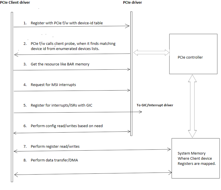
### **客户端与 PCI 驱动程序操作流程示例**

下图展示了 PCIe 客户端驱动程序为客户端配置 PCIe 驱动程序所遵循的顺序。

<Frame>
  <img src="https://mintcdn.com/qualcomm-staging/uWQLnBcS9sxlZhgB/System/Interfaces/images/client_driver_to_pci_controller.png?fit=max&auto=format&n=uWQLnBcS9sxlZhgB&q=85&s=78332480ad02245c284623b9693e523f" alt="PCIe 设备连接链路" width="776" height="665" data-path="System/Interfaces/images/client_driver_to_pci_controller.png" />
</Frame>

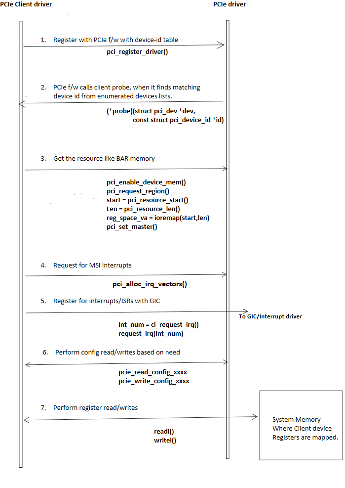
### **客户端与 PCI 驱动程序高层调用流程示例**

下图展示了 PCIe 客户端驱动程序与 PCIe 驱动程序之间的高层调用流程和调用详细信息。
<Frame>
  <img src="https://mintcdn.com/qualcomm-staging/uWQLnBcS9sxlZhgB/System/Interfaces/images/client_driver_to_pci.png?fit=max&auto=format&n=uWQLnBcS9sxlZhgB&q=85&s=dbfe604493b2ecfa340cf56e66674b0e" alt="PCIe 设备连接链路" width="699" height="987" data-path="System/Interfaces/images/client_driver_to_pci.png" />
</Frame>