> ## Documentation Index
> Fetch the complete documentation index at: https://dragonwingdocs-staging.qualcomm.com/llms.txt
> Use this file to discover all available pages before exploring further.
# 设置设备
> 在刷写 Qualcomm Linux 之后,连接串行控制台,验证软件版本,然后在 IQ-8275 EVK 上选择 USB (ADB)、Wi-Fi 或 Ethernet 作为主机到设备的持续连接方式。
在[刷写 Qualcomm Linux](./update-software/overview) 之后,使用本页内容启动设备。首先通过调试串行控制台登录并验证软件版本。之后,根据您的环境选择以下**一种**连接方式:
| 选项 | 适用场景 |
| ------------- | -------------------------- |
| **USB (ADB)** | 无可用网络;主机与设备之间直接使用 USB 线缆连接 |
| **Wi-Fi** | 无线访问;通过网络 SSH 登录设备 |
| **Ethernet** | 有线网络访问;通过网络 SSH 登录设备 |
如果您**尚未**刷写设备,请先从 [**更新软件**](./update-software/overview) 开始。
## 设置调试 UART
调试 UART 为您提供进入设备的串行控制台,这是刷机后登录和检查设备的主要方式。
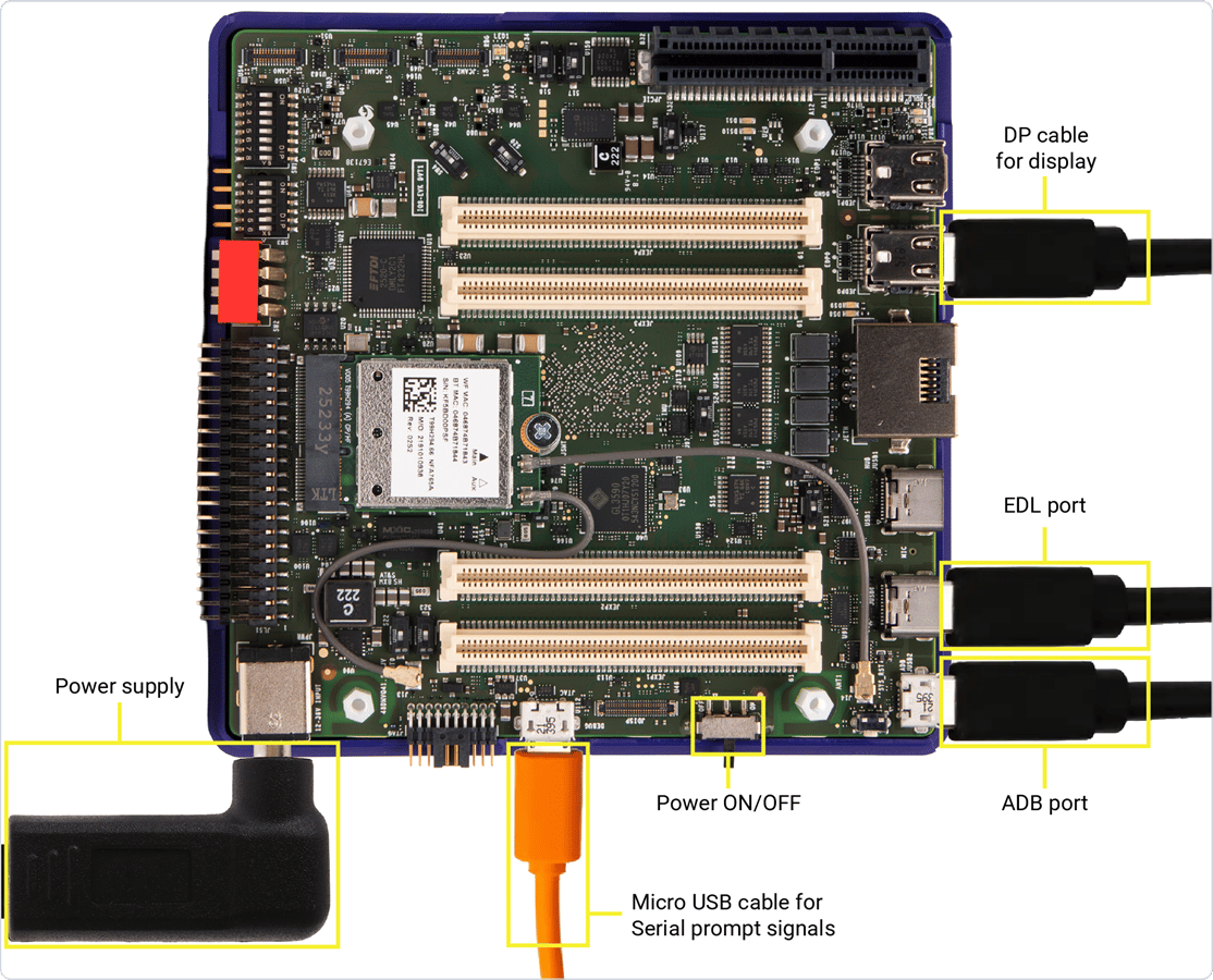
1. 将 micro-USB 线缆的一端连接到 IQ-8275 EVK 上的 micro-USB 端口。
2. 将另一端连接到您的主机。
 3. 根据主机操作系统打开串行控制台:
安装 `screen`:
```shell theme={null}
sudo apt update
sudo apt install screen
```
列出串行设备:
```shell theme={null}
ls /dev/ttyUSB*
```
**示例输出:**
```shell theme={null}
/dev/ttyUSB0 /dev/ttyUSB1 /dev/ttyUSB2 /dev/ttyUSB3
```
IQ-8275 EVK 的板载适配器提供四个串行设备;**主控制台是第二个**(`/dev/ttyUSB1`)。以 115200 波特率打开它:
```shell theme={null}
sudo screen /dev/ttyUSB1 115200
```
在打开 UART 控制台会话之前,请确认没有其他进程正在使用该串行端口。多个应用程序访问同一个 UART 设备可能导致挂起或控制台输出不一致。
3. 根据主机操作系统打开串行控制台:
安装 `screen`:
```shell theme={null}
sudo apt update
sudo apt install screen
```
列出串行设备:
```shell theme={null}
ls /dev/ttyUSB*
```
**示例输出:**
```shell theme={null}
/dev/ttyUSB0 /dev/ttyUSB1 /dev/ttyUSB2 /dev/ttyUSB3
```
IQ-8275 EVK 的板载适配器提供四个串行设备;**主控制台是第二个**(`/dev/ttyUSB1`)。以 115200 波特率打开它:
```shell theme={null}
sudo screen /dev/ttyUSB1 115200
```
在打开 UART 控制台会话之前,请确认没有其他进程正在使用该串行端口。多个应用程序访问同一个 UART 设备可能导致挂起或控制台输出不一致。
要识别当前正在使用串行端口的进程,请运行
* `sudo lsof /dev/ttyUSB1`
如果发现任何残留的 `screen` 或 `minicom` 会话,请使用以下命令终止它们
* `sudo killall screen`
* `sudo killall minicom`
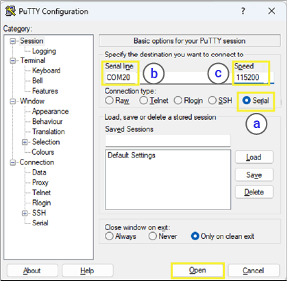
1. 下载 [**PuTTY**](https://putty.software/) 并完成安装。
2. 打开 PuTTY 并选择 **Serial**。
3. 将 **Serial line** 设置为在**设备管理器**中检测到的 COM 端口,速度设置为 **115200**。
FTDI 适配器提供多个 COM 端口。Converter B(**第二个**功能端口)承载 Main Domain 控制台。右键单击每个 COM 端口 → **属性** → 查看 **位置** 字段以进行识别。
如果未检测到 UART 端口,请安装 FTDI 驱动:
* x86 和 Arm:[FTDI VCP 驱动](https://ftdichip.com/drivers/vcp-drivers/)
 列出串行设备:
```shell theme={null}
ls /dev/cu.*
```
连接 micro-USB 线缆后,板载 FT4232H 四路 UART 控制器会提供四个串行接口(T0-T3)。T1 接口(显示为 **/dev/cu.usbserial-device\_unique\_serial\_number-T1**)用作**主串行调试控制台**。其余接口(T0、T2 和 T3)保留用于其他通信和调试用途。找到您的设备节点(T1),并使用 screen 命令以 115200 波特率打开:
```shell theme={null}
screen /dev/cu.usbserial-NNPMP271002T1 115200
```
4. 按 **Enter** 键调出登录提示符,然后登录:
* **用户名:** `root`
* **密码:** `oelinux123`
## 验证软件版本
确认设备正在运行 Qualcomm Linux:
```shell theme={null}
cat /etc/os-release
```
**预期输出:**
```text theme={null}
ID=qcom-distro-sota
NAME="Qualcomm Linux Reference Distro(OTA-enabled)"
VERSION="2.0"
PRETTY_NAME="Qualcomm Linux Reference Distro (OTA-enabled) 2.0"
```
检查内核版本:
```shell theme={null}
uname -a
```
**预期输出:**
```text theme={null}
Linux iq-8275-evk 6.18.30-... #1 SMP PREEMPT ... aarch64 GNU/Linux
```
如果版本不匹配,或者您根本无法进入登录提示符,则说明镜像缺失或已过时。请返回 [**更新软件**](./update-software/overview) 并刷写最新的 Qualcomm Linux。
## 连接到设备
从以下选项中选择一种。三种方式都需要通过 UART 控制台执行初始设置命令(参见[设置调试 UART](#set-up-the-debug-uart))。完成首次设置后,USB (ADB) 提供直接的 USB shell;Wi-Fi 和 Ethernet 则允许您通过 SSH 连接。
ADB(Android Debug Bridge)为您提供进入设备的 USB shell。由于 `adbd` 默认处于禁用状态,您需要先通过 UART 启用一次,ADB 才能工作。
**1. 在 Ubuntu 主机上安装 ADB:**
```shell theme={null}
sudo apt install android-tools-adb android-tools-fastboot
```
验证:
```shell theme={null}
adb --version
```
对于 Windows 和 Mac 主机,请从 [**Android SDK platform tools**](https://developer.android.com/tools/releases/platform-tools#downloads) 安装 ADB
**2. 在设备上启用 adbd**(一次性操作,在 UART 控制台执行):
```shell theme={null}
touch /etc/usb-debugging-enabled
systemctl enable --now android-tools-adbd
```
**3. 连接并打开 shell:**
使用 USB Type-C 线缆将主机连接到设备。
```shell theme={null}
adb devices
adb shell
```
**示例输出:**
```text theme={null}
List of devices attached
68f592a device
```
**1. 连接到 Wi-Fi 网络**(在 UART 控制台执行):
```shell theme={null}
nmcli dev wifi list
nmcli dev wifi connect password
```
**示例** — 网络 `QualcommWiFi`,密码 `1234567890`:
```shell theme={null}
nmcli dev wifi connect QualcommWiFi password 1234567890
```
**示例输出:**
```text theme={null}
Device 'wlp1s0' successfully activated with 'd7b990bd-3b77-4b13-b239-b706553abaf8'.
```
**2. 获取设备 IP 地址:**
```shell theme={null}
ip addr show wlp1s0
```
**3. 从主机 SSH 登录**(必须在同一网络中):
```shell theme={null}
ssh root@
```
出现提示时输入密码 `oelinux123`。
使用以太网线缆将 EVK 上的 RJ45 端口连接到网络路由器。套件中不包含以太网线缆。
**1. 获取设备 IP 地址**(在 UART 控制台执行):
```shell theme={null}
ip addr show end0
```
输出中 `inet` 的值即为设备 IP 地址。
**2. 从主机 SSH 登录**(必须在同一网络中):
```shell theme={null}
ssh root@
```
**示例:**
```shell theme={null}
ssh root@192.168.0.222
```
出现提示时输入密码 `oelinux123`。
## 连接显示器
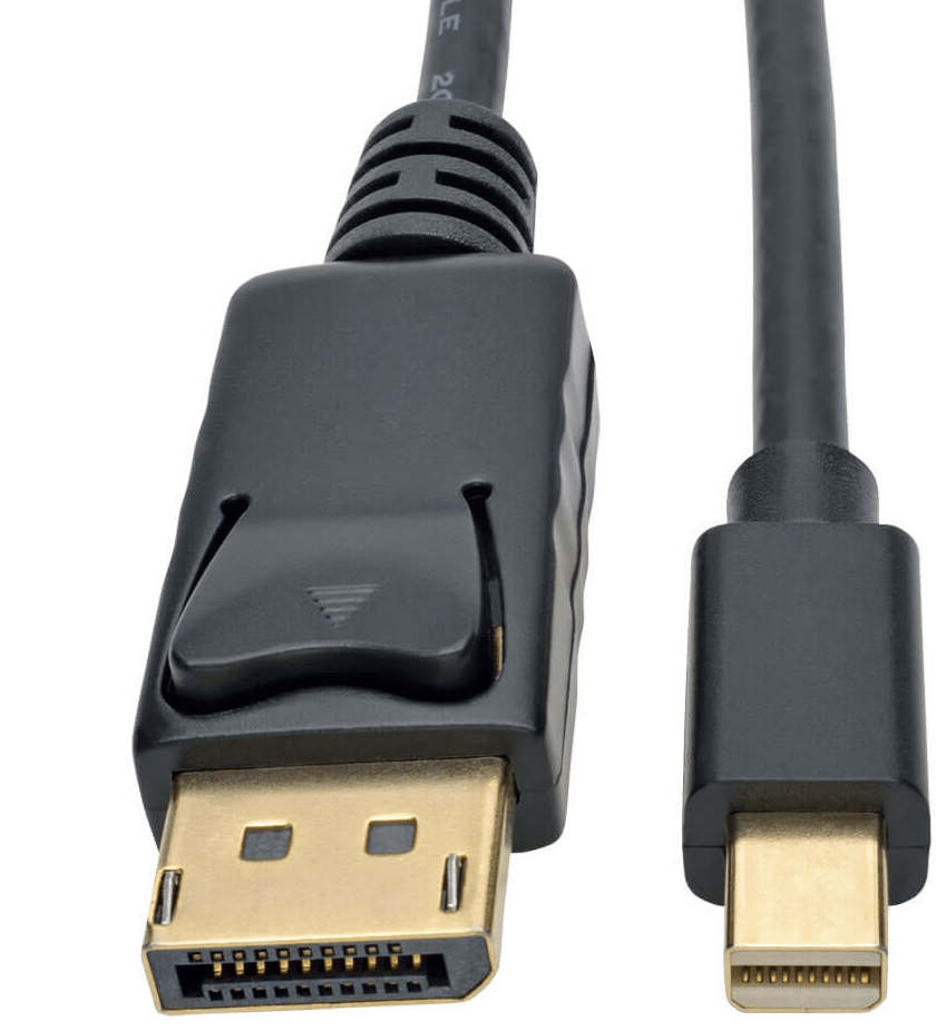
使用**有源** Mini DisplayPort 转 DisplayPort 线缆(随包装盒附带)或**有源** Mini DisplayPort 转 HDMI 适配器(不附带),将显示器连接到 EVK 上的 **DisplayPort0 (JEDP0)** 或 **JEDP1**。
显示输出仅可通过 DisplayPort 连接器实现。USB Type-C 端口不支持显示输出。
列出串行设备:
```shell theme={null}
ls /dev/cu.*
```
连接 micro-USB 线缆后,板载 FT4232H 四路 UART 控制器会提供四个串行接口(T0-T3)。T1 接口(显示为 **/dev/cu.usbserial-device\_unique\_serial\_number-T1**)用作**主串行调试控制台**。其余接口(T0、T2 和 T3)保留用于其他通信和调试用途。找到您的设备节点(T1),并使用 screen 命令以 115200 波特率打开:
```shell theme={null}
screen /dev/cu.usbserial-NNPMP271002T1 115200
```
4. 按 **Enter** 键调出登录提示符,然后登录:
* **用户名:** `root`
* **密码:** `oelinux123`
## 验证软件版本
确认设备正在运行 Qualcomm Linux:
```shell theme={null}
cat /etc/os-release
```
**预期输出:**
```text theme={null}
ID=qcom-distro-sota
NAME="Qualcomm Linux Reference Distro(OTA-enabled)"
VERSION="2.0"
PRETTY_NAME="Qualcomm Linux Reference Distro (OTA-enabled) 2.0"
```
检查内核版本:
```shell theme={null}
uname -a
```
**预期输出:**
```text theme={null}
Linux iq-8275-evk 6.18.30-... #1 SMP PREEMPT ... aarch64 GNU/Linux
```
如果版本不匹配,或者您根本无法进入登录提示符,则说明镜像缺失或已过时。请返回 [**更新软件**](./update-software/overview) 并刷写最新的 Qualcomm Linux。
## 连接到设备
从以下选项中选择一种。三种方式都需要通过 UART 控制台执行初始设置命令(参见[设置调试 UART](#set-up-the-debug-uart))。完成首次设置后,USB (ADB) 提供直接的 USB shell;Wi-Fi 和 Ethernet 则允许您通过 SSH 连接。
ADB(Android Debug Bridge)为您提供进入设备的 USB shell。由于 `adbd` 默认处于禁用状态,您需要先通过 UART 启用一次,ADB 才能工作。
**1. 在 Ubuntu 主机上安装 ADB:**
```shell theme={null}
sudo apt install android-tools-adb android-tools-fastboot
```
验证:
```shell theme={null}
adb --version
```
对于 Windows 和 Mac 主机,请从 [**Android SDK platform tools**](https://developer.android.com/tools/releases/platform-tools#downloads) 安装 ADB
**2. 在设备上启用 adbd**(一次性操作,在 UART 控制台执行):
```shell theme={null}
touch /etc/usb-debugging-enabled
systemctl enable --now android-tools-adbd
```
**3. 连接并打开 shell:**
使用 USB Type-C 线缆将主机连接到设备。
```shell theme={null}
adb devices
adb shell
```
**示例输出:**
```text theme={null}
List of devices attached
68f592a device
```
**1. 连接到 Wi-Fi 网络**(在 UART 控制台执行):
```shell theme={null}
nmcli dev wifi list
nmcli dev wifi connect password
```
**示例** — 网络 `QualcommWiFi`,密码 `1234567890`:
```shell theme={null}
nmcli dev wifi connect QualcommWiFi password 1234567890
```
**示例输出:**
```text theme={null}
Device 'wlp1s0' successfully activated with 'd7b990bd-3b77-4b13-b239-b706553abaf8'.
```
**2. 获取设备 IP 地址:**
```shell theme={null}
ip addr show wlp1s0
```
**3. 从主机 SSH 登录**(必须在同一网络中):
```shell theme={null}
ssh root@
```
出现提示时输入密码 `oelinux123`。
使用以太网线缆将 EVK 上的 RJ45 端口连接到网络路由器。套件中不包含以太网线缆。
**1. 获取设备 IP 地址**(在 UART 控制台执行):
```shell theme={null}
ip addr show end0
```
输出中 `inet` 的值即为设备 IP 地址。
**2. 从主机 SSH 登录**(必须在同一网络中):
```shell theme={null}
ssh root@
```
**示例:**
```shell theme={null}
ssh root@192.168.0.222
```
出现提示时输入密码 `oelinux123`。
## 连接显示器
使用**有源** Mini DisplayPort 转 DisplayPort 线缆(随包装盒附带)或**有源** Mini DisplayPort 转 HDMI 适配器(不附带),将显示器连接到 EVK 上的 **DisplayPort0 (JEDP0)** 或 **JEDP1**。
显示输出仅可通过 DisplayPort 连接器实现。USB Type-C 端口不支持显示输出。
 给设备上电,并确认显示器显示预期的启动输出。
## 连接蓝牙外设
使用 `bluetoothctl` 配对并连接蓝牙键盘或鼠标。
1. 打开蓝牙管理器:
```shell theme={null}
bluetoothctl
```
2. 打开电源并开始扫描:
```shell theme={null}
power on
scan on
```
3. 等待您的设备出现,并记下其 MAC 地址:
```text theme={null}
[NEW] Device F8:7D:76:9D:9B:6B MyKeyboard
```
4. 配对、信任并连接:
```shell theme={null}
pair F8:7D:76:9D:9B:6B
trust F8:7D:76:9D:9B:6B
connect F8:7D:76:9D:9B:6B
```
5. 停止扫描并退出:
```shell theme={null}
scan off
exit
```
设备在以后启动时会自动重新连接。有关 Wi-Fi 和蓝牙的完整详情,请参见 [**Wi-Fi 与蓝牙**](./peripherals-interfaces/WiFi-BT)。
## SBC(单板计算机)模式
要将 EVK 用作带有键盘、鼠标和显示器的独立计算机:
给设备上电,并确认显示器显示预期的启动输出。
## 连接蓝牙外设
使用 `bluetoothctl` 配对并连接蓝牙键盘或鼠标。
1. 打开蓝牙管理器:
```shell theme={null}
bluetoothctl
```
2. 打开电源并开始扫描:
```shell theme={null}
power on
scan on
```
3. 等待您的设备出现,并记下其 MAC 地址:
```text theme={null}
[NEW] Device F8:7D:76:9D:9B:6B MyKeyboard
```
4. 配对、信任并连接:
```shell theme={null}
pair F8:7D:76:9D:9B:6B
trust F8:7D:76:9D:9B:6B
connect F8:7D:76:9D:9B:6B
```
5. 停止扫描并退出:
```shell theme={null}
scan off
exit
```
设备在以后启动时会自动重新连接。有关 Wi-Fi 和蓝牙的完整详情,请参见 [**Wi-Fi 与蓝牙**](./peripherals-interfaces/WiFi-BT)。
## SBC(单板计算机)模式
要将 EVK 用作带有键盘、鼠标和显示器的独立计算机:
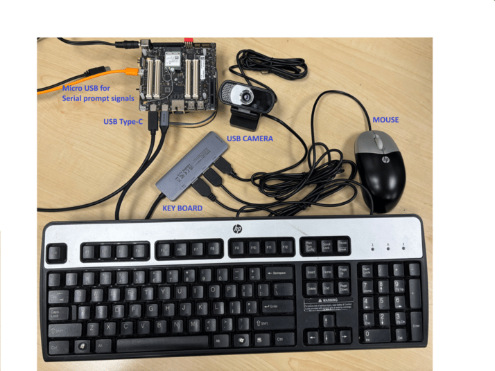 * **电源:** 连接 12 V 适配器。
* **串行控制台:** 通过 micro-USB 连接主机以获取 UART 日志(设置完成后可选)。
* **USB 集线器:** 将带电源的 USB 集线器连接到 USB Type-C 端口,以支持多个外设。
* **键盘和鼠标:** 插入 USB 集线器。
* **USB 摄像头:** 连接到 USB 集线器(必须符合 UVC 规范)。
* **MIPI 摄像头:** 连接到板上的 MIPI CSI 连接器。
* **显示器:** Mini DisplayPort 转 DisplayPort 线缆,或有源 Mini DisplayPort 转 HDMI 适配器。
## IQ8275-AC (20 TOPS) 模拟
AC SKU 模拟功能允许 IQ8275 **AA SKU 硬件**平台以 **IQ8275 AC SKU** 的频率和特性配置运行。该模拟通过 QTEE devcfg 文件中的单个 OEM 配置属性启用 — 无需更改固件源代码,也无需重新构建 TZ 核心组件。
**何时使用此功能:**
* 在 AC SKU 芯片可用之前,在 AA SKU 硬件板上对 IQ8275 AC SKU 软件进行启动和验证。
* 在预生产环境中测试 AC SKU 的频率和特性配置。
**支持的模拟:**
| 模拟 | 属性值 | 说明 |
| ------------- | --- | ----------------------------- |
| 禁用(默认) | `0` | 硬件 SKU 检测 — 正常生产行为 |
| IQ8275 AC SKU | `3` | 在 AA 硬件上应用 IQ8275 AC 的频率和特性配置 |
**注意**
此功能仅供**预生产使用**。在所有生产设备上必须将其禁用(`0`)。
**使用方法**
### 步骤 1:打开 OEM 配置文件
```
trustzone_images/ssg/securemsm/trustzone/qsee/mink/oem/config/monaco/oem_config.xml
```
### 步骤 2:找到 `OEM_softsku_sim_config` 属性
该属性位于 `/tz/oem` 设备节点下:
```xml theme={null}
0
```
### 步骤 3:启用 AC SKU 模拟
将值从 `0` 改为 `3` 以启用 IQ8275 AC SKU 模拟:
```xml theme={null}
3
```
### 步骤 4:重新构建并刷写
为 IQ8275 重新构建 DevCfg 镜像并刷写到目标板:
```
Build cmd: python3 trustzone_images/build/ms/build_all.py CHIPSET=monaco devcfg_iot
```
DevCfg 镜像的构建说明请参见 [https://dragonwingdocs.qualcomm.com/System/Security/enable-device-configurations-from-qualcomm-tee。](https://dragonwingdocs.qualcomm.com/System/Security/enable-device-configurations-from-qualcomm-tee。)
刷写更新后的 DevCfg 二进制文件:
可以使用 fastboot 命令刷写更新后的 DevCfg 镜像
```
fastboot flash devcfg_a trustzone_images/build/ms/bin/FAQAANAA/devcfg_iot.mbn
```
完整的构建刷写说明请参见 [https://dragonwingdocs.qualcomm.com/Key-Documents/Flash-Guide/flash-with-qdl。](https://dragonwingdocs.qualcomm.com/Key-Documents/Flash-Guide/flash-with-qdl。)
**禁用模拟(生产环境)**
要禁用模拟并恢复正常的硬件 SKU 检测,请将该属性设回 `0`:
```xml theme={null}
0
```
重新构建并重新刷写。如果文件中不存在该属性,驱动程序会自动默认为 `0` — 不应用任何模拟。
**重要说明**
* **生产设备必须将此属性设置为 `0`。** 在生产硬件上启用模拟可能导致错误的频率/特性配置。
* 此功能**仅适用于 IQ8275**。本版本不支持其他平台。
* 本版本仅支持值 `3`(IQ8275 AC SKU)。其他非零值保留供未来版本使用,不会产生任何效果。
## 后续步骤
* [探索外设与接口](./peripherals-interfaces/peripheral_interface_overview)
* **电源:** 连接 12 V 适配器。
* **串行控制台:** 通过 micro-USB 连接主机以获取 UART 日志(设置完成后可选)。
* **USB 集线器:** 将带电源的 USB 集线器连接到 USB Type-C 端口,以支持多个外设。
* **键盘和鼠标:** 插入 USB 集线器。
* **USB 摄像头:** 连接到 USB 集线器(必须符合 UVC 规范)。
* **MIPI 摄像头:** 连接到板上的 MIPI CSI 连接器。
* **显示器:** Mini DisplayPort 转 DisplayPort 线缆,或有源 Mini DisplayPort 转 HDMI 适配器。
## IQ8275-AC (20 TOPS) 模拟
AC SKU 模拟功能允许 IQ8275 **AA SKU 硬件**平台以 **IQ8275 AC SKU** 的频率和特性配置运行。该模拟通过 QTEE devcfg 文件中的单个 OEM 配置属性启用 — 无需更改固件源代码,也无需重新构建 TZ 核心组件。
**何时使用此功能:**
* 在 AC SKU 芯片可用之前,在 AA SKU 硬件板上对 IQ8275 AC SKU 软件进行启动和验证。
* 在预生产环境中测试 AC SKU 的频率和特性配置。
**支持的模拟:**
| 模拟 | 属性值 | 说明 |
| ------------- | --- | ----------------------------- |
| 禁用(默认) | `0` | 硬件 SKU 检测 — 正常生产行为 |
| IQ8275 AC SKU | `3` | 在 AA 硬件上应用 IQ8275 AC 的频率和特性配置 |
**注意**
此功能仅供**预生产使用**。在所有生产设备上必须将其禁用(`0`)。
**使用方法**
### 步骤 1:打开 OEM 配置文件
```
trustzone_images/ssg/securemsm/trustzone/qsee/mink/oem/config/monaco/oem_config.xml
```
### 步骤 2:找到 `OEM_softsku_sim_config` 属性
该属性位于 `/tz/oem` 设备节点下:
```xml theme={null}
0
```
### 步骤 3:启用 AC SKU 模拟
将值从 `0` 改为 `3` 以启用 IQ8275 AC SKU 模拟:
```xml theme={null}
3
```
### 步骤 4:重新构建并刷写
为 IQ8275 重新构建 DevCfg 镜像并刷写到目标板:
```
Build cmd: python3 trustzone_images/build/ms/build_all.py CHIPSET=monaco devcfg_iot
```
DevCfg 镜像的构建说明请参见 [https://dragonwingdocs.qualcomm.com/System/Security/enable-device-configurations-from-qualcomm-tee。](https://dragonwingdocs.qualcomm.com/System/Security/enable-device-configurations-from-qualcomm-tee。)
刷写更新后的 DevCfg 二进制文件:
可以使用 fastboot 命令刷写更新后的 DevCfg 镜像
```
fastboot flash devcfg_a trustzone_images/build/ms/bin/FAQAANAA/devcfg_iot.mbn
```
完整的构建刷写说明请参见 [https://dragonwingdocs.qualcomm.com/Key-Documents/Flash-Guide/flash-with-qdl。](https://dragonwingdocs.qualcomm.com/Key-Documents/Flash-Guide/flash-with-qdl。)
**禁用模拟(生产环境)**
要禁用模拟并恢复正常的硬件 SKU 检测,请将该属性设回 `0`:
```xml theme={null}
0
```
重新构建并重新刷写。如果文件中不存在该属性,驱动程序会自动默认为 `0` — 不应用任何模拟。
**重要说明**
* **生产设备必须将此属性设置为 `0`。** 在生产硬件上启用模拟可能导致错误的频率/特性配置。
* 此功能**仅适用于 IQ8275**。本版本不支持其他平台。
* 本版本仅支持值 `3`(IQ8275 AC SKU)。其他非零值保留供未来版本使用,不会产生任何效果。
## 后续步骤
* [探索外设与接口](./peripherals-interfaces/peripheral_interface_overview)