> ## Documentation Index
> Fetch the complete documentation index at: https://dragonwingdocs-staging.qualcomm.com/llms.txt
> Use this file to discover all available pages before exploring further.
# DIP Switches, Ports and Interfaces
## Ports and Interfaces
 ## DIP Switches
The following images show the location of the DIP switches on the mainboard.
## DIP Switches
The following images show the location of the DIP switches on the mainboard.
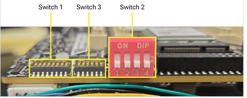
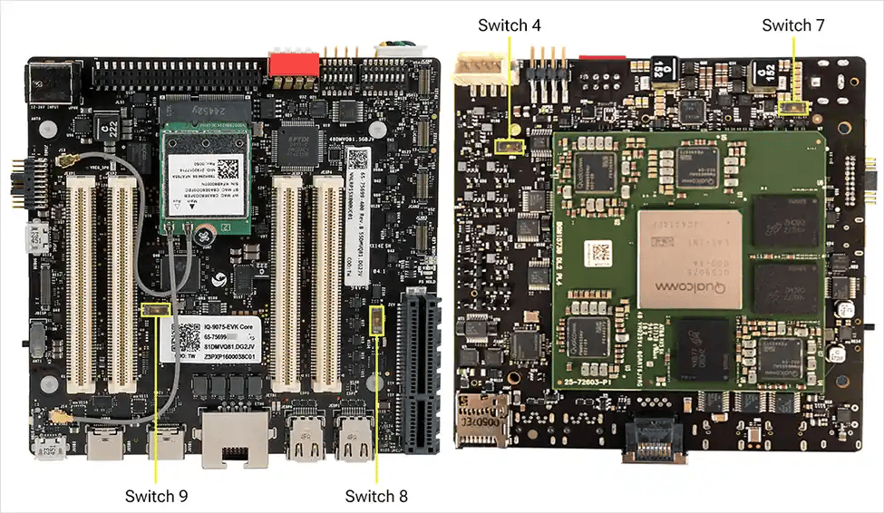 All functions on the mainboard operate with no DIP switch changes. The large red switch is for EDL/Fastboot; the smaller switches below are for mezzanines.
| Switch | Connection when ON | Connection when OFF (factory default) |
| - | - | - |
| SW1-1 | PCIe0 routed to mezzanine | PCIe0 connected to mainboard Wi-Fi module |
| SW1-2 | PCIe1 routed to mezzanine | PCIe1 connected to mainboard PCIe connector |
| SW1-3 | SDIO routed to mezzanine | SDIO routed to mainboard SD card |
| SW1-4 | DSI routed to mainboard flex connector | DSI routed to mezzanine |
| SW1-5 | CSI0 routed to mezzanine | CSI0 routed to mainboard CSI flex connector |
| SW1-6 | CSI1 routed to mezzanine | CSI1 routed to mainboard CSI flex connector |
| SW1-7 | CSI2 routed to mezzanine | CSI2 routed to mainboard CSI flex connector |
| SW2-1 | Main domain forced USB boot/EDL | No impact |
| SW2-2 | Main domain fast boot | No impact |
| SW2-3 | Main domain and Sail domain forced USB boot/EDL (combined) | No impact |
| SW2-4 | Sail domain Fastboot mode | No impact |
| SW3-1 | OSPI routed to mezzanine | OSPI connected to onboard memory for MCU |
| SW3-2 | Force MD and MCU PS\_HOLD | No impact |
| SW3-3 | Watchdog disabled | RAM dump enabled |
| SW3-4 | Boot from eMMC (located on interface and mezzanine) | Boot from UFS |
| SW3-5 | EUD enable | No impact |
| SW3-6 | Skip MD BIST | No impact |
| SW4-1 | PWM-MODE for fan set to low | PWM-MODE for fan set to high |
| SW7-1 | RGMII voltage select 2.5V | RGMII voltage select 1.8V |
| SW8-1 | USB to M.2 connector for NFA765 module on mezzanine | USB to M.2 connector for NFA765 module on mainboard |
| SW9-1 | SAIL CAN GPIOs routed to mezzanine | SAIL CAN GPIOs routed to JLS1 connector |
**SW2-1** is not enabled in software. **SW2-3** puts both domains into EDL mode simultaneously — required for software download.
## Other Buttons and Switches
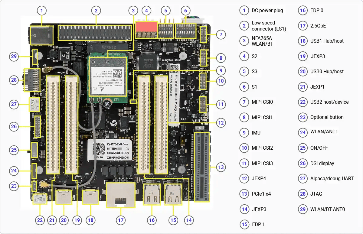
* The **side-mounted slide/toggle switch** (position 25) is the **main power on/off** control. To power cycle or reset the device, flip the switch — no button press or hold is required.
* A **small push button** (position 26) is currently **inactive**. It is connected to **GPIO 6** and reserved for a future software feature.
All functions on the mainboard operate with no DIP switch changes. The large red switch is for EDL/Fastboot; the smaller switches below are for mezzanines.
| Switch | Connection when ON | Connection when OFF (factory default) |
| - | - | - |
| SW1-1 | PCIe0 routed to mezzanine | PCIe0 connected to mainboard Wi-Fi module |
| SW1-2 | PCIe1 routed to mezzanine | PCIe1 connected to mainboard PCIe connector |
| SW1-3 | SDIO routed to mezzanine | SDIO routed to mainboard SD card |
| SW1-4 | DSI routed to mainboard flex connector | DSI routed to mezzanine |
| SW1-5 | CSI0 routed to mezzanine | CSI0 routed to mainboard CSI flex connector |
| SW1-6 | CSI1 routed to mezzanine | CSI1 routed to mainboard CSI flex connector |
| SW1-7 | CSI2 routed to mezzanine | CSI2 routed to mainboard CSI flex connector |
| SW2-1 | Main domain forced USB boot/EDL | No impact |
| SW2-2 | Main domain fast boot | No impact |
| SW2-3 | Main domain and Sail domain forced USB boot/EDL (combined) | No impact |
| SW2-4 | Sail domain Fastboot mode | No impact |
| SW3-1 | OSPI routed to mezzanine | OSPI connected to onboard memory for MCU |
| SW3-2 | Force MD and MCU PS\_HOLD | No impact |
| SW3-3 | Watchdog disabled | RAM dump enabled |
| SW3-4 | Boot from eMMC (located on interface and mezzanine) | Boot from UFS |
| SW3-5 | EUD enable | No impact |
| SW3-6 | Skip MD BIST | No impact |
| SW4-1 | PWM-MODE for fan set to low | PWM-MODE for fan set to high |
| SW7-1 | RGMII voltage select 2.5V | RGMII voltage select 1.8V |
| SW8-1 | USB to M.2 connector for NFA765 module on mezzanine | USB to M.2 connector for NFA765 module on mainboard |
| SW9-1 | SAIL CAN GPIOs routed to mezzanine | SAIL CAN GPIOs routed to JLS1 connector |
**SW2-1** is not enabled in software. **SW2-3** puts both domains into EDL mode simultaneously — required for software download.
## Other Buttons and Switches
* The **side-mounted slide/toggle switch** (position 25) is the **main power on/off** control. To power cycle or reset the device, flip the switch — no button press or hold is required.
* A **small push button** (position 26) is currently **inactive**. It is connected to **GPIO 6** and reserved for a future software feature.